


Valving The Head Assembly
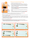
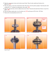
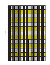
1. Clamp the head assembly in the vice (B1).
2. Set up a clean, low lint paper towel on the bench next to the vice.
3. Using a marker, label the upper right hand corner of the paper towel
with an “R” (rebound) and the lower right hand corner of the paper
towel with a “C” (compression).
4. Using a 1/2“ boxed end wrench, remove the piston nut and washer
from the head assembly
(B2). Place the nut and washer between the
“R” and “C” on the paper towel.
5. Remove the rebound disc travel limiter along with the rebound disc
stack.
6. Remove all of the discs from the travel limiter &set the rebound disc
travel limiter directly across from the “R” on the paper towel
(B3).
B1
Clamp
the head
assembly
into the vice
B
B
B2
Remove
piston nut
and washer
from the head
assembly
B6B5
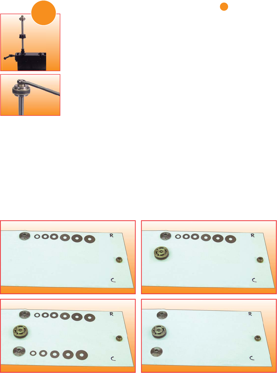
7. Remove the piston and place on the paper towel across from the piston nut and washer (B4).
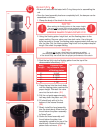
8. Remove the compression travel limiter along with the disc stack from the rod.
9. Remove all of the discs from the travel limiter & set the compression disc travel limiter directly across from
the “C” on the paper towel
(B5).
10. Using dial calipers, carefully measure each shim’s diameter and thickness. For rebuilds, replace each shim
with same size new shim. For revalving, refer to Valve Code Sheet. *Note: .594 OD x .020 shim is constant,
and remains on travel limiter at all times.
11. Remove shims from paper towel
(B6).
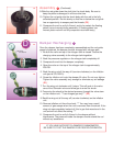
12. Place the new rebound valve discs on the paper towel directly across from the “R”, and the new
compression discs directly across from the “C”. Put the discs in order from top to bottom starting with the
disc that will be placed closest to the face of the disc travel limiter
(B5).
B3 B4