


27
TK-760G/762G
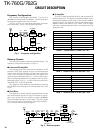
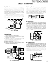
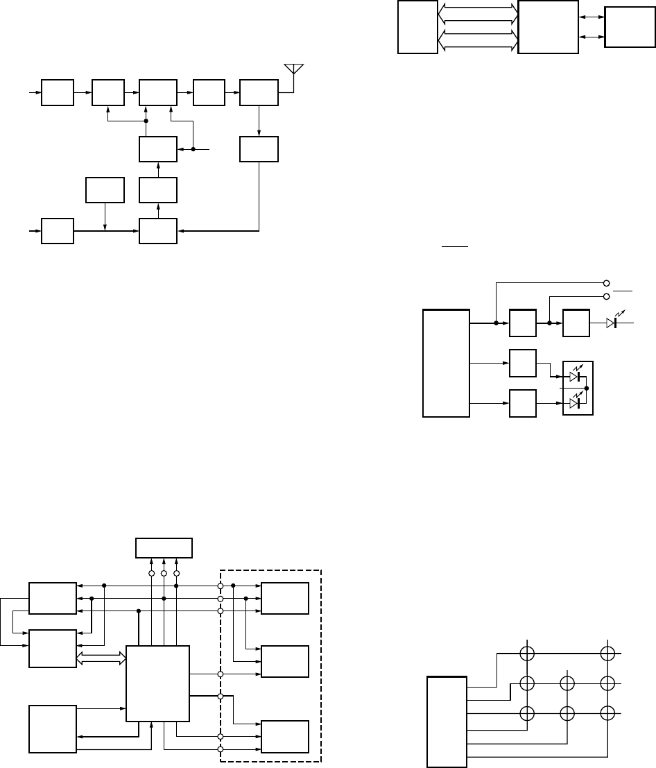
■ APC Circuit
The automatic transmission power control (APC) circuit
detects part of a power module output with a diode (D35,
D36) and applies a voltage to IC15. IC15 compares the APC
control voltage (PC) generated by the D/A converter (IC6)
and DC amplifier (IC7) with the detection output voltage to
control Q31 and Q32, generates DB voltage from B voltage,
and stabilizes transmission output.
The APC circuit is configured to protect over current of
the power module due to fluctuations of the load at the an-
tenna end and to stabilize transmission output at voltage
and temperature variations.
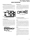
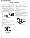
■ Memory Circuit
The transceiver has a 2M-bit (256k x 8) flash ROM
(IC501) and an 8k-bit EEPROM (IC505). The flash ROM con-
tains firmware programs, data and user data which is pro-
grammed with the FPU. The EEPROM contains adjustment
data. The CPU (IC502) controls the flash ROM through an
external address bus and an external data bus. The CPU
controls the EEPROM through two serial data lines.
Control Circuit
The CPU carries out the following tasks:
1) Controls the shift register (IC9, IC510) AF MUTE, WIDE/
NARROW, T/R KEY outputs.
2) Adjusts the AF signal level of the audio processor (IC508)
and turns the filter select compounder on or off.
3) Controls the DTMF decoder (IC511).
4) Controls the LCD assembly display data.
5) Controls the PLL (IC3).
6) Controls the D/A converter (IC6) and adjusts the volume,
modulation and transmission power.
Fig. 9 APC circuit
Fig. 10 Control circuit
Fig. 11 Memory circuit
CIRCUIT DESCRIPTION
RF
AMP
Q22
RF
AMP
Q25
POWER
AMP
IC400
APC
DRIVER
Q32
DB
+B
Q31
PRI
DRIVER
DC
AMP
IC7
ANT
SW
D34
LPF
ANT
POWER
DET
D35,36
IC15
APC
CONTROL
D16
PC
IC6
23pin
Q33
TEMP
PROTECT
IC6
D/A
converter
IC3
PLL
IC9
Shift
register
IC510
Shift
register
OE
LCDCS
CNTCK
CNTDT
AFCLR
AFMSKE
AFSTB
IC508
Audio
processor
IC511
DTMF
DECO.
IC502
CPU
TX-RX UNIT
LCD ASSY
AFREG2
AFREG1
DTMDAT
DTMCLK
DTMSTD
DAST
PLST
PLDT
PLCK
SCL
SDA
IC502
CPU
ADDRESS BUS
DATA BUS
IC501
FLASH
ROM
IC505
EEPROM
Q506
SW
Q508
SW
Q504
SW
Q505
SW
MBL
LED1
LED0
IC510
Shift
register
D521
GRN
RED
D509~514
MBL
MBL
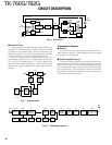
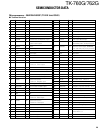
■ Key Matrix Circuit
The TK-760G/762G front panel has function keys. Each
of them is connected to a cross point of a matrix of the KIN0
to KOUT2 ports of the microprocessor. The KOUT0 to
KOUT2 ports are always high, while the KIN0 to KIN2 ports
are always low.
The microprocessor monitors the status of the KIN0 to
KOUT2 ports. If the state of one of the ports changes, the
microprocessor assumes that the key at the matrix point
corresponding to that port has been pressed.
IC502
CPU
KIN0
KIN1
KIN2
KOUT0
KOUT1
KOUT2
D/A GRP
DN
CH
DN
CH
UP
GRP
UP
A
VOL
DN
VOL
UP
Fig. 12 Display circuit
Fig. 13 Key matrix circuit
■ Display Circuit
The CPU (IC502) controls the shift register (IC510) and
display LEDs. When the LED1 line goes high when the
transceiver is busy, Q508 turns on and the green LED on
D521 lights. In transmit mode, the LED0 line goes high,
Q504 turns on and the red light lights. Backlighting LEDs for
the key operation unit (D509~D514) and LCD are provided.
When the MBL line goes high, Q506 turns on, then Q505
turns on, and the key illumination LED lights. A voltage is
applied to the MBL line to turn on the LCD backlight.