


3
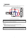
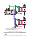
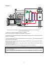
Wiring
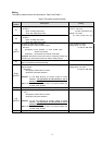
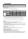
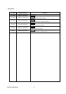
The safety related terminals are described in Table.2 and Table.3
Table.2 The safety related terminals
Terminal
Symbol
Description Rating
S1
For input of safety stop channel1.
S1-SC is
Open: In safety stop mode.
Short: Non safety stop mode.
S2
For input of safety stop channel2.
S2-SC is
Open: In safety stop mode.
Short: Non safety stop mode.
Input resistance:4.7kΩ
Current : 4 to 6 mA
(In case of shorted to SC)
Voltage : 21 to 26 V
(In case of open from SC)
SO
(SAFE)
As output for safety stop condition.
SO terminal type is ‘Open collector output’.
SO-SC is
OFF(Open): Drive enabled, or drive shutoff (with
internal circuit fault)
ON(Close): Drive shutoff (no internal circuit fault)
Important: SO terminal should be used for monitoring safety stop
condition only. SO terminal cannot be used for safety function.
Load: 24VDC/0.1A max.
Voltage drop: 3.4V max.
(In case of ‘ON’ state)
SC
Common terminal for S1, S2, SO terminals.
*SC is connected terminal SD internally.
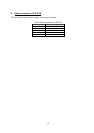
RUN
(SAFE2)
As output for failure detection and alarm. RUN terminal type is ‘Open
collector output’.
RUN-SE is
OFF(Open): Detect failure or Alarm.
ON(Close): No failure detected.
Attention: To use RUN terminal for monitor output of failure
detection, The parameter No.190 should be set 81
(Safety monitor 2).
Note: This terminal can be used for alarm or to prevent restart only,
no other safety function.
Load: 24VDC/0.1A max.
Voltage drop: 3.4V max.
(In case of ‘ON’ state)
SE
Common terminal for safety RUN terminal.
A,C
(SAFE2)
As output for failure detection. A,C terminal type is ‘Relay output’.
A-C is
OFF(Open): Detect failure or Alarm.
ON(Close): No failure detected.
Attention: To use A,C terminal for monitor output of failure
detection, The parameter No.192 should be set 81
(Safety monitor 2).
Note: This terminal can be used for alarm or to prevent restart only,
no other safety function.
Load: 30VDC/0.3A max.
SD
Signal ground