


6
START
+24V
K1
X0 X1
COM0 COM1
24G
Internal
Safety
Circuit
XS0 XS1 Z10 Z00 Z20
Z11 Z01 Z21
K2
DC24V
QS90SR2SN-Q
MITSUBISHI MELSEC Safety relay module
S2
S1
SC
FR-D700
A(SAFE2)
CPU
RY
B
C
U V W
Gate
Driver
Gate
Driver
IGBTs
S2
S1
SC
FR-D700
CPU
RY
B
C
Gate
Driver
Gate
Driver
IGBTs
U V W
+24V
+24V
+24V
+24V
GG
GG
A
(SAFE2)
+24V
+24V
IM
IM
R/L1 S/L2 T/L3
R/L1 S/L2 T/L3
Emergency
stop button
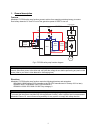
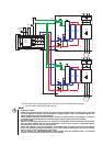
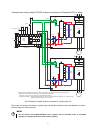
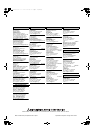
Fig.4 Example when using multiple FR-D740-EC inverters manufactured in August
2010 or later for the safety stop function
NOTE
• For Europe model:
When using the safety stop function, do not connect the FR-D700 series manufactured in July 2010
or before together with the one manufactured in August 2010 or later. If connected together, the
safety stop function may not work properly.
When the FR-D700 series manufactured in July 2010 or before must be used together, connect an
electronic component (diode) to the inverter output shutoff signals (terminal S1 and S2).
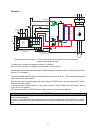
• For Japan model:
When using the safety stop function, do not connect the FR-D700 series manufactured in December
2010 or before together with the one manufactured in January 2011 or later. If connected together,
the safety stop function may not work properly.
When the FR-D700 series manufactured in December 2010 or before must be used together,
connect an electronic component (diode) to the inverter output shutoff signals (terminal S1 and S2).
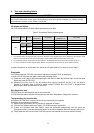
Refer to page 7 for the specification of the diode.
• Do not connect the FR-E700-SC/NC/NF series together with the FR-D700 series. If connected
together, the safety stop function does not work properly.