


7
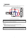
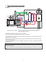
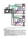
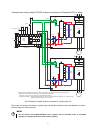
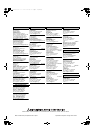
• Example when using multiple FR-D700 inverters manufactured in December 2010 or before
START
Emergency stop button
+24V
K1
X0 X1
COM0 COM1
24G
Internal
Safety
Circuit
XS0 XS1 Z10 Z00 Z20
Z11 Z01 Z21
K2
DC24V
QS90SR2SN-Q
MITSUBISHI MELSEC Safety relay module
S2
S1
SC
FR-D700
CPU
RY
B
C
U V W
Gate
Driver
Gate
Driver
IGBTs
IM
S2
S1
SC
FR-D700
CPU
RY
B
C
Gate
Driver
Gate
Driver
IGBTs
IM
U V W
*
*
*
*
+24V
+24V
+24V
+24V
GG
GG
A(SAFE2)
A
(SAFE2)
+24V
+24V
R/L1 S/L2 T/L3
R/L1 S/L2 T/L3
* When connecting multiple inverters, use a diode on each safety input terminal to prevent a malfunction due to
undesirable current. Refer to the following for the specification of the diode.
Diode type : P-N junction type (Do not use a Schottky barrier diode.)
Electronic specification - Peak reverse voltage (Vrrm) : 50V or more, Peak forward voltage (Vf) : 1V or less (at 5mA),
Effective forward current (If) : 100mA or more
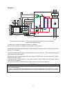
Fig.5 Example of multiple inverters connected to a safety relay unit
The number of inverters connected to a safety relay unit should be decided under considerations of output
terminal rating of a safety relay unit.
NOTE
• Do not connect the FR-E700-SC/NC/NF series together with the FR-D700 series. If connected
together, the safety stop function does not work properly.