


4
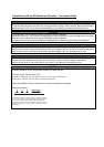
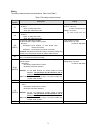
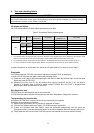
Table.3 Truth table of Safety related signals
Input power S1-SC S2-SC
Internal safety
circuit fault *1
SO (SAFE)
RUN or A-C
(SAFE2) *2 *3
Drive state
OFF - - - OFF(Open) OFF(Open) Drive shutoff (Safe state)
No failure OFF(Open) ON(Close) Drive enable
Short Short
Detected OFF(Open) OFF(Open) Drive shutoff (Safe state)
No failure ON(Close) ON(Close) Drive shutoff (Safe state)
Open Open
Detected OFF(Open) OFF(Open) Drive shutoff (Safe state)
Short Open N/A OFF(Open) OFF(Open) Drive shutoff (Safe state)
ON
Open
Short N/A OFF(Open) OFF(Open) Drive shutoff (Safe state)
" N/A " denotes a condition where circuit fault does not apply.
*1 At an internal safety circuit fault, E.SAF or E.CPU is displayed on the operation panel. SA is displayed on the operation panel
while S1 and S2 signals are both open and the safety function operates (without internal safety circuit fault).
*2 To use RUN terminal for monitor output of failure detection, the parameter No.190 should be set 81 (Safety monitor 2).
*3 To use A,C terminal for monitor output of failure detection, the parameter No.192 should be set 81 (Safety monitor 2).
Wire and ferrule specification
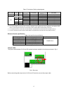
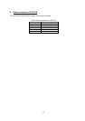
Table.4 wire and ferrule specification
Wire size (mm
2
) Ferrule with insulation collar * Crimping tool *
0.3 / 0.5 AI 0,5-10WH
0.75 AI 0,75-10GY
1 AI 1-10RD
1.25 / 1.5 AI1,5-10BK
0.75 (combined 2 wire) AI TWIN 2 X 0,75-10GY
CRIMPFOX 6
*Ferrules and tools are distributed by Phoenix Contact.
Jumper cable
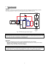
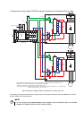
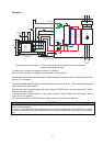
The jumper cable between S1,S2 and SC terminal has been installed in the factory as shown in Fig.2.
Fig.2. Short wire
Before connecting safety input wire to S1,S2 and SC terminal, remove this jumper cable.
AMAM