


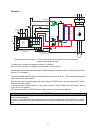

5
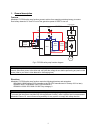
3. Example of safety system configuration
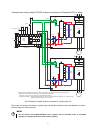
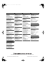
Example 1
S2
S1
SC
FR-D700
START
+24V
K1
A(SAFE2)
CPU
X0 X1
COM0 COM1
24G
Internal
Safety
Circuit
XS0 XS1 Z10 Z00 Z20
Z11 Z01 Z21
K2
DC24V
RY
B
C
QS90SR2SN-Q
MITSUBISHI MELSEC Safety relay module
Gate
Driver
Gate
Driver
STF
PC*
STOP
STOP
STF
+24V
+24V
GG
+24V
R/L1
* If the control logic is SINK logic, the common
terminal is terminal SD.
Emergency
stop button
S/L2 T/L3
U V W
IM
IGBTs
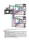
Fig.3 Safety system example 1 – STOP asynchronous with emergency stop button and fault
detection through A-C output.
For safety stop, configure the wiring as shown in Fig.3 above.
Note: the above wiring is configured to prevent restart in case of a fault.
The parameter No.192 (A,B,C terminal function selection) must be set to ‘81’. This setting makes the A-C
output to open in case of failure.
After the power-up, to reset the safety stop mode, press the START switch, and also press the STF switch,
then start the motor rotation.
In the above configuration, after reset of emergency stop button, drive will be in safe-state until START
switch is pressed.
CAUTION
To prevent restart in case of recovering from input power loss of drive, 3-wired connection for STF/STOP
control is recommended.
In case of 2-wire connection and using latching type switch to short between STF and SD/PC for starting,
ensure the compliance with safety requirement for the restarting when the drive recover from input power
loss.