


164
Orientation (Pr. 350 to Pr. 362, Pr. 393 to Pr. 399)
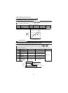
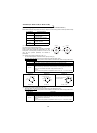
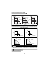
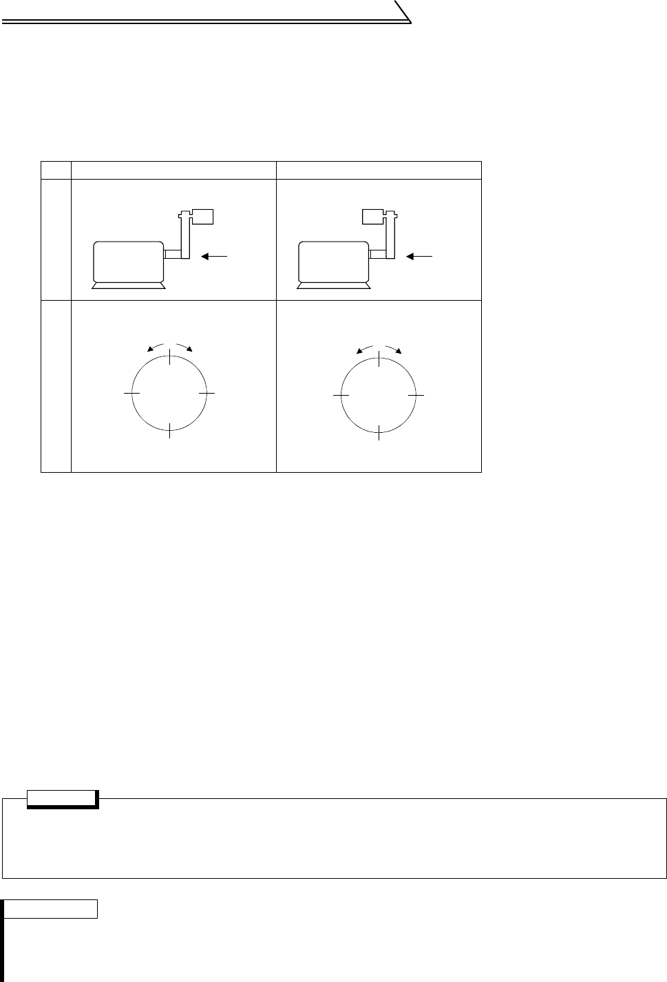
(4) Fine adjustment of the orientation stop position (Pr. 361 "position shift"
(factory setting: 0))
The orientation stop position will deviate by the value set x 360° / Pr. 851 "number of encoder pulses" x4.
Finely adjust the position by changing this setting value in 10 increments.
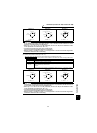
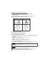
The orientation stop position will differ according to the direction that the encoder is installed in.
(Refer to the drawings below.)
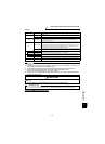
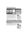
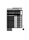
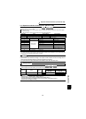
(5) Adjustment of the servo rigidity
z Pr. 396 "orientation speed gain (P term)" (factory setting: 60)
z Pr. 397 "orientation speed integral time" (factory setting: 0.333)
z Pr. 398 "orientation speed gain (D term)" (factory setting: 1)
z Pr. 362 "orientation position loop gain" (factory setting: 10)
• To increase the servo rigidity*
1
during orientation stop in Pr. 396 or Pr. 397, adjust with the following procedures.
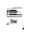
1) Increase the Pr. 362
"orientation position loop gain" value to the extent that rocking does not occur during
orientation stop.
2) Increase Pr. 396 and Pr. 397 at the same rate.
Generally adjust Pr. 396 in the range from 10 to 100, and Pr. 397 from 0.1 to 1.0s.
(Note that these do not need to be set to the same rate.)
<Example>
When the Pr. 396 value is multiplied by 1.2, divide the Pr. 397 value by 1.2.
If vibration occurs during orientation stop, the scale cannot be raised any higher.
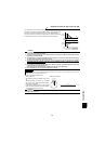
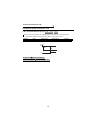
3) Pr. 398 is the lag/advance compensation gain.*
2
The limit cycle can be prevented by increasing the value, and the running can be stopped stably. However, the
torque in regard to the position deviation will drop, and the motor will stop with deviation.
Case 1 Case 2
Installation directionNormal orientation
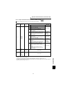
POINT
Application of lag/advance control and PI control
PI control can be applied by setting Pr. 398 to 0. Normally, the lag/advance control is selected. Use PI control in
the following cases.
When using a machine with a high spindle stationary friction torque and requires a stopping position precision.
REMARKS
*1. Servo rigidity: This is the response when a position control loop is configured.
When the servo rigidity is raised, the holding force will increase, the running will stabilize, but vibration will occur easily.
When the servo rigidity is lowered, the holding force will drop, and the setting time will increase.
*2. Limit cycle*:This is a phenomenon that generates ± continuous vibration centering on the target position.
*3. Rocking: Movement in which return occurs if the stopping position is exceeded.
Motor
Belt
Encoder
A
Motor
Belt
Encoder
A
View from A
Foward
Reverse
3072
(270°)
1024
(90°)
2048
(180°)
View from A
Forward
Reverse
3072
(270°)
1024
(90
°)
2048
(180
°)