12
Wiring
2.2 Wiring
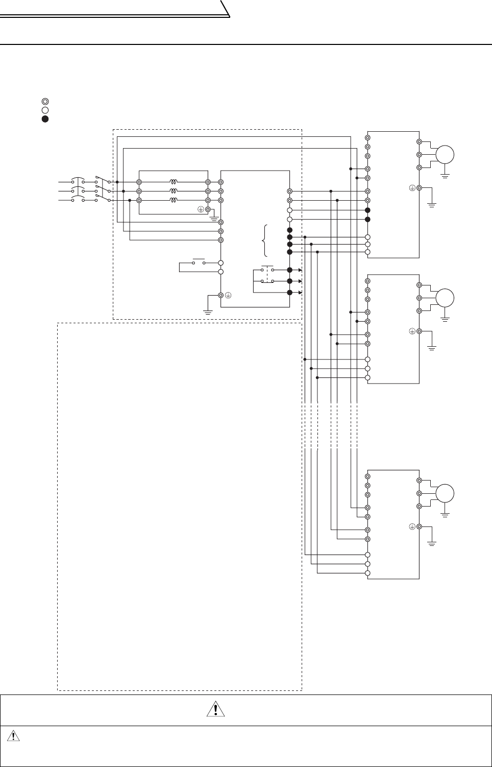
2.2.1 Terminal connection diagram
Be sure to connect terminal RDY of the FR-CV to the X10 or MRS signal assigned terminal of the
inverter, and connect terminal SE of the FR-CV to terminal SD of the inverter. Without proper
connecting, FR-CV will be damaged.
MCNFB
R/L11
FR-CVL
S/L21
T/L31
R2/L12
S2/L22
T2/L32
R2/L1
S2/L2
T2/L3
R/L11
S/L21
T/MC1
P/L+
N/L-
RES
SD
SD
P24
SE
RDYB
RS0
A
B
C
R/L1
S/L2
T/L3
R1/L11
S1/L21
P/+
N/-
PC
SD
X10 (MRS)
RES
SD
FR-A720
U
V
W
IM
(Note 1)
R/L1
S/L2
T/L3
R1/L11
S1/L21
P/+
N/-
X10 (MRS)
RES
SD
FR-A720
U
V
W
IM
R/L1
S/L2
T/L3
R1/L11
S1/L21
P/+
N/-
X10 (MRS)
RES
SD
FR-A720
U
V
W
IM
(Note 3)
FR-CV
RDYA
3-phase
AC power supply
Open collector
outputs
(Note 1)
(Note 3)
(Note 1)
(Note 3)
Main circuit terminal
Control circuit input terminal
Control circuit output terminal
R
S
T
(Note 4)
(Note 4)
(Note 5)
(Note 2)
(Note 7)
(Note 2)
(Note 7)
(Note 2)
(Note 7)
Note : 1. Never connect a power supply to the inverter terminals R, S, T.
Such a connection, even if accidental, will damage the inverter
and power regeneration common converter.
2. Match the polarities of the P and N terminals by connecting
terminal P of the inverter to terminal P of the power
regeneration common converter and terminal N of the inverter
to terminal N of the power regeneration common converter as
shown in the connection example. Incorrect matching of
the polarities of the P and N terminals will result in damage
to the inverter.
Do not remove a jumper across terminal P/+ and P1.
3. For the FR-A700, F700, A500, F500 and V500 series, remove
the jumpers across terminals R-R1 and S-S1, and connect
power supply to terminals R1, S1 for the control circuit. For the
FR-E700, D700, E500, S500, C500 and F500J series, the
inverter does not have terminals R1, S1. So you do not need to
make this connection.
4. When wiring the dedicated stand-alone reactor and power
regeneration common converter as well as when wiring
the power supply and terminals R/L11, S/L21, T/MC1, strictly
observe the wiring order as shown in the connection example
(match phase sequence of the power supply).
A wrong connection will damage the power regeneration
common converter.
Do not insert an MCCB nor MC. The power regeneration
common converter functions abnormally.
5. Make sure terminals R/L11, S/L21, T/MC1 are connected to
the power supply. Running the inverter without connecting
these terminals will damage the power regeneration common
converter.
6. Since power to the inverter is supplied by terminals P and N,
set Pr.30 to 2 (for use with a high power factor converter, power
regeneration common converter) for the FR-A700, F700, A500,
F500 and V500 series. This setting disables the built-in brake
resistor.
7. For the FR-A700, F700, E700, D700, A500, F500 and V500
series inverter, assign the X10 signal to any of input terminals to
use the inverter.
8. You can connect up to six inverters to one power regeneration
common converter.
9. Use sink logic (factory setting) when the FR-CV is connected.
The FR-CV cannot be connected when source logic is selected.
CAUTION


