


41
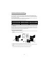
Precautions for Maintenance and Inspection
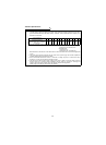
PROTECTIVE FUNCTIONS
3
*Values in parentheses indicate those for 400V class.
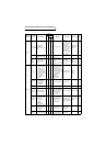
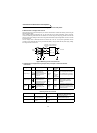
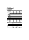
Power supply side power
P
1
At R2/L1, S2/L2 and T2/L3
and across R2/L1-S2/L2,
S2/L2-T2/L3, and T2/L3-R2/
L1
Electrodynamic type
single-phase wattmeter
P
1 = W11 + W12 + W13
(3-wattmeter method)
Power supply side power
factor Pf
1
Calculate after measuring power supply voltage, power supply side current and power supply side
power.
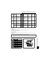
Converter output side
voltage
Across P/L+-N/L-
Moving-coil type
(such as tester)
Converter LED display lit
1.35
× V1
Maximum 380V (760V) during
regenerative operation
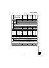
Reset Across RES (+) -SD
Moving-coil type (Tester,
etc. may be used)
(Internal resistance:
50k
Ω or larger)
20 to 30VDC when
open.
ON voltage: 1V or
less (Note)
SD is common.
Alarm signal
Across A-C
Across B-C
Moving-coil type
(such as tester)
Continuity check
<At OFF> <At ON>
Across A-C: Discontinuity Continuity
Across B-C: Continuity Discontinuity
Note: When a 24VDC power supply is connected across P24-SD.
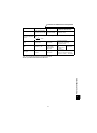
Item Measuring Point Measuring Instrument
Remarks
(Reference Measured Value) *
3
V
1
×
I
1
P1
Pf
1
100
×
%