


26
Other wiring
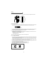
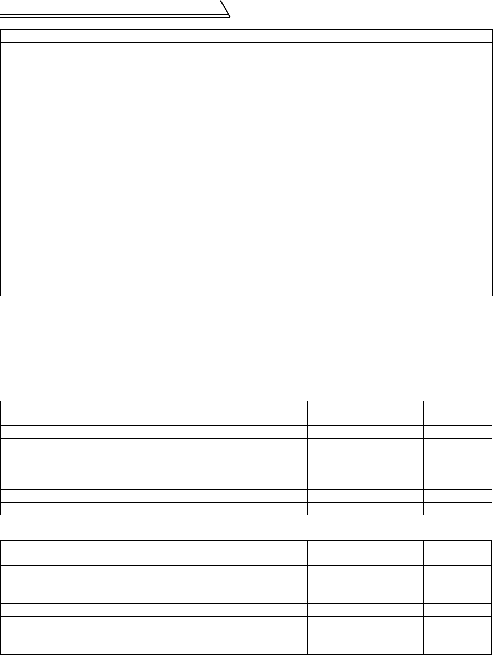
2.4.3 Peripheral devices
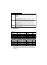
(1) Selection of peripheral devices
Refer to the following list and prepare appropriate peripheral devices:
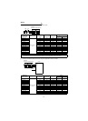
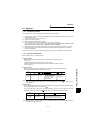
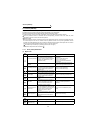
1) 200V class
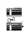
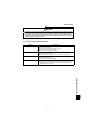
2) 400V class
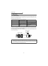
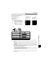
4) 5) 6)
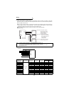
When the signal cables are run in parallel with or bundled with the power cables, magnetic and static
induction noise may be propagated to the signal cables to effect the devices and the following measures
must be taken:
(1) Install easily affected devices as far away as possible from the power regeneration common
converter.
(2) Run easily affected signal cables as far away as possible form the power regeneration common
converter.
(3) Do not run the signal cables and power cables (power regeneration common converter I/O cables) in
parallel with each other and do not bundle them.
(4) Use shielded cables for signal cables and power cables and run them in individual metal conduits to
reduce further effects.
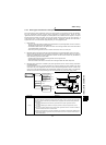
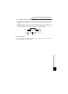
7)
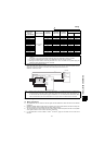
When the power supplies of the peripheral devices are connected to the power supply of the power
regeneration common converter within the same line, power regeneration common converter-generated
noise may flow back through the power supply cables to misoperate the devices and the following
measures must be taken:
(1) Install the radio noise filter (FR-BIF) to the power cables (input cables) of the power regeneration
common converter.
(2) Install the line noise filter (FR-BLF, FR-BSF01) to the power cables (I/O cables) of the power
regeneration common converter.
8)
When a closed loop circuit is formed by connecting the peripheral device wiring to the power regeneration
common converter, leakage current may flow through the ground cable of the power regeneration
common converter to affect the device. In such a case, disconnection of the ground cable of the device
may cause the device to operate properly.
Power Regeneration
Common Converter Type
Applicable Capacity
(kW (HP))
Power Supply
Capacity (kVA)
Rated current of
Circuit Breaker
Magnetic
Contactor
FR-CV-7.5K (-AT) 7.5 (10) 17 100AF 60A S-N35
FR-CV-11K (-AT) 11 (15) 20 100AF 75A S-N50
FR-CV-15K (-AT) 15 (20) 28 225AF 125A S-N65
FR-CV-22K (-AT) 22 (30) 41 225AF 175A S-N95
FR-CV-30K (-AT) 30 (40) 52 225AF 225A S-N125
FR-CV-37K 37 (50) 66 400AF 250A S-N150
FR-CV-55K 55 (75) 100 400AF 400A S-N220
Power Regeneration
Common Converter Type
Applicable Capacity
(kW (HP))
Power Supply
Capacity (kVA)
Rated current of
Circuit Breaker
Magnetic
Contactor
FR-CV-H7.5K (-AT) 7.5 (10) 17 30AF 30A S-N20
FR-CV-H11K (-AT) 11 (15) 20 50AF 50A S-N20
FR-CV-H15K (-AT) 15 (20) 28 100AF 60A S-N25
FR-CV-H22K (-AT) 22 (30) 41 100AF 100A S-N50
FR-CV-H30K (-AT) 30 (40) 52 225AF 125A S-N65
FR-CV-H37K 37 (50) 66 225AF 150A S-N80
FR-CV-H55K 55 (75) 100 225AF 200A S-N125
Note: 1. For installations in the United States or Canada, the circuit breaker must be inverse time or
instantaneous trip type.
2. When the breaker on the primary side of the power regeneration common converter tripped, check for
wiring fault (e.g.short circuit), damage to internal parts of the inverter (power regeneration common
converter), etc. Identify the cause of the breaker trip, then power on the breaker after removing the
cause of the trip.
Noise Path Measures