


CHAPTER 1 ND-70684 (E)
Page 6
Revision 1.0
OVERVIEW
General Service Conditions
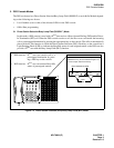
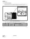
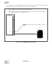
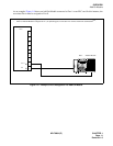
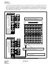
As shown in Figure 1-4, the cable distance allowed includes the 25-pair installation cable.
Figure 1-4 Cable Distance Definition
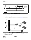
5. General Service Conditions
The following service conditions apply to both a DSS/BLF and Add-On Module.
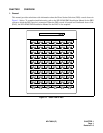
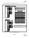
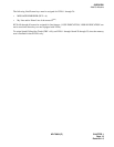
1. A DSS/BLF and an Add-On Module can coexist on one circuit card. Figure 1-5 illustrates an example of
port allocation on an ELC circuit card.
Figure 1-5 Example of Port Allocation on an ELC Card
2. DSS consoles, their associated D
term
s, and stations which are to be assigned to the DSS keys must belong
to the same Inter Module Group.
25-Pair installation cable
MDF
Cable Distance between PBX and DSS
Rosette
DSS Console
PBX
Champ
Connector
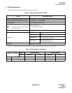
Station Wire
0.4 mm (.051 in) (26 AWG)
0.5 mm (.019 in) (24 AWG)
REAR VIEW
ADM
D
term
D
term
D
term
ADM
D
term
DSS/BLF
ELC
LV
7
6
5
4
3
2
1
0
ADM
D
term
D
term
D
term
ADM
D
term
DSS/BLF
No terminal can be wired to this port.
NEC
Feature
Feature
...
... ... ...
...
...
...
... ...
...
... ...
...
...
...
Speaker
Answer
Transfer
Hold
4
5
6
4
GHI
5
JKL
6
MNO
7
8
9
7
PQRS
8
TUV
9
WXYZ
0
#
#
0
OPER
Exit
Help
MIC
Feature
1
1
2
3
2
ABC
3
DEF
...
...
...
...
...
Recall
Conf
Redial
NEC
Feature
Feature
...
... ...
...
...
...
...
... ... ...
...
...
...
... ...
Speaker
Answer
Transfer
Hold
4
5
6
4
GHI
5
JKL
6
MNO
7
8
9
7
PQRS
8
TUV
9
WXYZ
0
#
#
0
OPER
Exit
Help
MIC
Feature
1
1
2
3
2
ABC
3
DEF
...
... ...
... ...
Recall
Conf
Redial
NEC
Feature
Feature
...
... ...
... ...
...
... ...
... ...
... ... ...
... ...
Speaker
A
n
swer
T
r
a
ns
f
er
Hold
4
5
6
4
GHI
5
JKL
6
MNO
7
8
9
7
PQRS
8
TUV
9
WXYZ
0
#
#
0
OPER
Exit
Help
MIC
Feature
1
1
2
3
2
ABC
3
DEF
...
...
... ... ...
Recall
Conf
Redial
NEC
Feature
...
... ...
... ...
...
... ...
... ...
... ...
...
... ...
Speaker
Answer
Transfer
Hold
4
5
6
4
GHI
5
JKL
6
MNO
7
8
9
7
PQRS
8
TUV
9
WXYZ
0
#
#
0
OPER
Exit
Help
MIC
Feature
1
1
2
3
2
ABC
3
DEF
...
...
... ... ...
Recall
Conf
Redial