


ND-70684 (E) CHAPTER 2
Page 15
Revision 1.0
CHAPTER 2 INSTALLATION PROCEDURE
This chapter describes the installation procedure for the DSS console. It includes a connection diagram and the
locations of the cable leads.
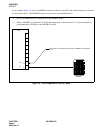
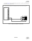
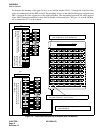
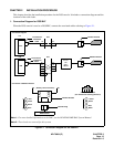
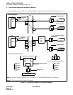
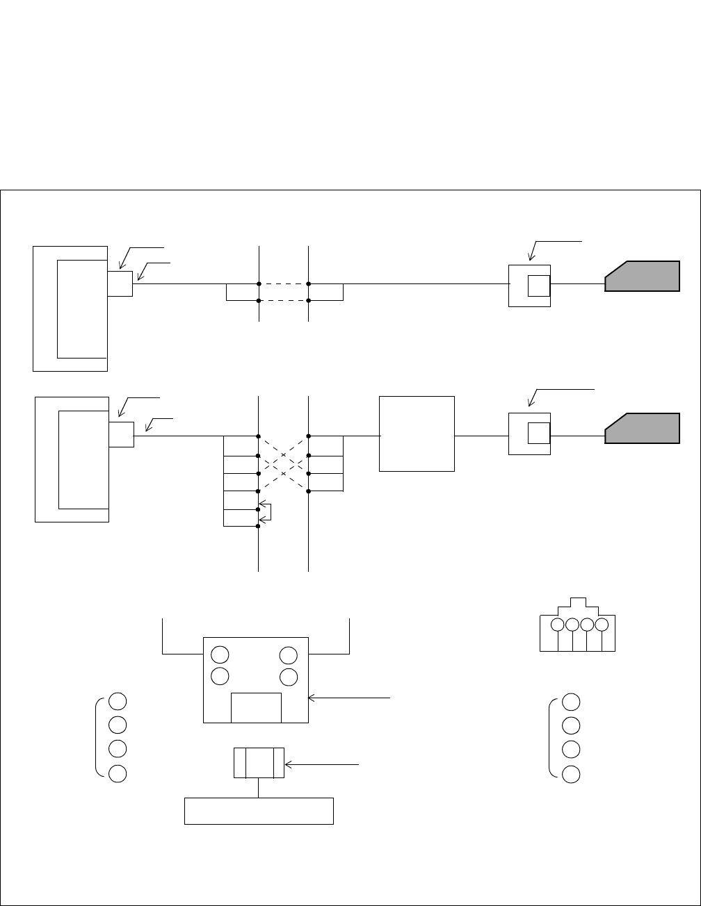
1. Connection Diagram for DSS/BLF
When the DSS console is used as a DSS/BLF, connect the associated cables referring to Figure 2-1.
Figure 2-1 Connection Diagram for the DSS/BLF
Note 1:
For more detailed information on the DAU, see the NEAX2400 IMX DAU System Manual.
Note 2:
These leads are not used for this system.
PIM
PIM
MDF
MDF
A0
A0
B0
B0
TA
TB
RA
RB
RA
TB
TA
RB
Pout A
Pout B
Distributed
Access
Unit
(DAU)
Note 1
Note 2
LT Connector
Installation
Cable
Modular Rosette
DSS/BLF
Modular Rosette
DSS/BLF
ELC
DAI
LT Connector
Installation
Cable
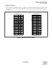
Connection Diagram
1
2
3
4
1
2
3
4
A0 B0(Polarity can be reversed.)
- Red
-Green
-Black
-Blue
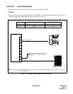
DSS Console
1 2 3 4
1
2
3
4
- Yellow
-Green
-Red
-Black
4-Core Modular Jack
(As viewed from inserting direction.)
Modular Plug
Modular Rosette
Connection of Modular Rosette