


CHAPTER 1 ND-70684 (E)
Page 12
Revision 1.0
OVERVIEW
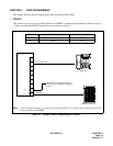
Add-On Module
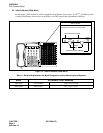
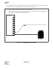
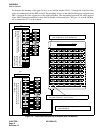
To designate the meaning of the upper 24 keys on an Add-On Module, FKYs 17 through 40 of the D
term
that
works in combination with the DSS are used. The remaining 36 keys on the Add-On Module are assigned using
FKYs 5 through 40 of the original port of the Add-On Module. The relationship between KYN, which appears
in the AKYD command, and 60 keys on an Add-On Module is illustrated below. In Figure 1-9, an Add-On Mod-
ule is connected to LV 1 as an example.
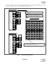
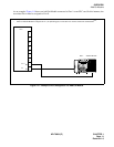
Figure 1-9 Line/Feature Access Key Allocation (Add-ON Module)
00 0504030201
54 5958575655
48 5352515049
42 4746454443
36 4140393837
30 3534333231
24 2928272625
18 2322212019
12 1716151413
06 1110090807
D
term
LV 0
KYN of
AKYD
39
38
37
36
35
34
24
23
33
21
20
19
18
17
16
15
14
Add-On Module
LV1
KYN of
AKYD
39
38
37
36
35
34
14
13
12
11
10
9
8
7
6
5
3
2
1
• Among 40 KYNs, KYN 5-40 are used
for allocating Line/Feature keys to the
Add-On Module.
• These FKYs are used for allocating
desired Line/Feature keys to the Add-
On Module
KYN of
DSS
34
33
32
31
30
29
60
59
58
57
56
55
54
53
KYN of
DSS
24
23
22
21
20
19
8
7
6
5
4
3
2
1
• The upper 30 DSS keys are assigned as the first port
(even-numbered LV), in this example LV0.
40
4
3
2
1
• These FKYs are
used for the Line/
Feature keys of
the original D
term
18
40
33
32
31
28
27
26
25
52
51
4
• The remaining lower 30 DSS keys are assigned as the second
port (odd-numbered LV), in this case LV1
• The Add-On Module is physically connected to the
odd-numbered LV.