


SECTION THREE — Installing the 491
PAGE 14 491 INSTALLATION MANUAL Revision A
Choosing a
mounting
location
Before any drilling or cutting takes place, carefully choose a mounting
location for the 491 module that meets the following criteria:
• where the transducer cable is kept securely away from other wires
• where the path for running the required electrical cabling is reason-
ably direct; keep in mind the different cable lengths
• where the 491 won’t be exposed to water
• where the status indicator (on the front of the 491) can be observed
for system testing and troubleshooting.
NEVER MOUNT THE 491 MODULE IN THE BILGE!
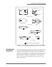
Mounting the
491
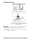
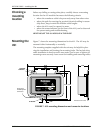
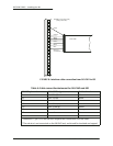
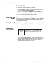
Figure 7 shows the mounting dimensions for the 491. The 491 may be
mounted either horizontally or vertically.
The mounting template supplied with the unit may be helpful in plan-
ning the installation and locating the mounting holes. The keyhole slots
make installation in hard-to-reach areas easier, but be sure to tighten all
mounting screws securely. Leave room for installing and removing cables.
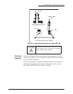
FIGURE 7: 491 mounting dimensions and connector locations
2.90
2.90
0.75
6.24
0.190 dia.
0.360 dia.
0.190 dia.
Dimensions in inches
5.80
8.78
7.22
2.35
491
Echo Sounder
DATA
BNT Marine Electronics
30 Sudbury Road
Acton MA 01720
800-628-4487
www.NorthstarNav.com
8–36 VDC
8 Watts
STATUS
POWER
TRANSDUCER
#2 Speed +V
#3 Speed Gnd
#7Thermistor
#6 Depth
Lo –
#9 Depth Shields
#1 Speed
Sig
#4Thermistor
#5 Depth
Lo +
#8 Depth Hi +
#10 Depth
Hi –
Allow space
for cabling from
connectors.