


SECTION THREE — Installing the 491
PAGE 18 491 INSTALLATION MANUAL Revision A
Connecting the 491
to a transducer
Transducers purchased from Northstar (see page 4) are shipped with a
connector installed. The following information is supplied for transducers
purchased elsewhere and for cases where it is necessary to remove and
reinstall the connector.
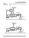
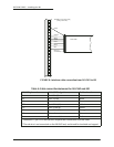
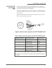
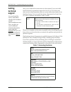
Figure 10 and Figure 11 below show how to install the connector on the
cable.
1. Slide the heat shrink tubing onto the transducer cable.
2. Slide the connector backshell onto the transducer cable.
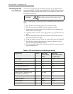
3. Prepare each wire for insertion into its solder cup by stripping it as
shown below and tinning it.
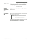
4. Carefully solder each wire to the appropriate cup as specified in the
table.
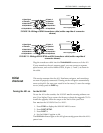
5. Slide the backshell down the wire and screw it onto the connector
body. It should be hand-tight.
6. Using the supplied screws, screw the strain relief onto the backshell.
7. Slide the heat shrink tubing onto the connector. Be sure to leave
room for the locking collar to retract.
8. Heat the shrink tubing until it shrinks around the connector provid-
ing a watertight seal.
CAUTION!
High voltage is present on the transducer wires!
Table 6: 491-to-transducer connector pin wiring
Signal name Pin no. Wire color
(Airmar B260
ONLY)
Wire color
(Airmar B44/B744V
and P66 ONLY)
Speed signal 1 N/A Green
Speed +V 2 N/A Red
Speed ground 3 N/A Bare
Thermistor (temperature) 4 Brown Brown
Depth 50 kHz + (unused on sin-
gle-frequency transducer)
5 Yellow N/A
Depth 50 kHz – (unused on sin-
gle-frequency transducer)
6 Blk/Wht N/A
Thermistor (temperature) 7 White White
Depth 200 kHz + 8 Blue Blue
Depth shields 9 Shields Shields
Depth 200 kHz – 10 Black Black