


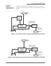

SECTION THREE — Installing the 491
491 INSTALLATION MANUAL Revision A PAGE 15
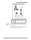
Wiring the 491
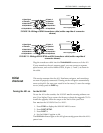
The majority of installation problems are caused by shortcuts taken with
system cables. When installing the 491, be sure that you:
• assemble connectors carefully
• don’t make sharp bends in the cables
• leave service and drip loops, so that moisture won’t run down the
cables and into the 491 or the navigator
• tie-wrap all cables to keep them secure
• if cables are shortened, lengthened (not recommended), or re-termi-
nated, seal all wiring splices
• prevent interference from the transducer cable
Electrical power
requirements
The 491 is a negative-ground system that is reverse-polarity and over-
voltage protected. The unit requires 8 to 36 VDC power at 8 Watts.
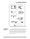
Connecting the 491
to ship’s power
The connection between ship’s power and the 491 requires the 10-foot
(3-meter) power cable supplied with the 491.
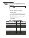
The wires in the power cable must be connected as follows (black and
white can be connected together at the power source):
• Red → Positive (+) (fused lead)
• Black → Negative (–)
• Green → Ground (earth)
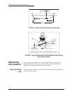
Connecting the 491
to the 961/962
The connection between the 961/962 and the 491 uses the 10-foot
(3-meter) data cable supplied with the 491. The cable connects to the P1
slot on the back of the navigator.
The cable is shipped with a round 6-pin connector that attaches to other
Northstar navigators. To install the 491 with a 961 or 962, you must cut
off and discard the 6-pin connector, and wire the cable as shown below.
Be sure you don’t cut off the 8-pin connector that plugs into the 491!
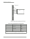
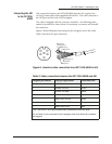
Figure 8 below illustrates the wiring at the 961/962 end of the cable.
Table 4 describes the pin’s functions.
CAUTION!
Make sure that fuse or circuit-breaker protection is
provided at the power source.
NOTE:
The 491 should be grounded to the vessel to eliminate interfer-
ence. Secure the green wire to the vessel’s nearest grounding
point. Without an earth grounding, performance may be degraded.