


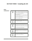

SECTION THREE — Installing the 491
PAGE 16 491 INSTALLATION MANUAL Revision A
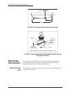
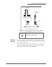
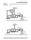
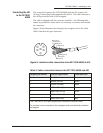
FIGURE 8: Interface cable connection from 961/962 to 491
Violet
Black
Blue
Brown
Orange
White
Green
Red (not
connected)
961/962 P1 Connector Plug
(Wiring Side View)
Data Cable
16
17
18
13
6
5
4
3
2
1
14
15
11
10
9
8
7
12
Table 4: Cable connection between the 961/962 and 491
961/962 pin number 961/962 P1 signal name Cable wire color
9 Port 3 In (A) Blue
10 Port 3 In (B) Black
11 Ground Brown
12* Port 3 Out (A) Violet
12* Port 3 Out (A) White
13 Port 3 Out (B) Orange
16 Ground Green
** Not connected Red
* Connector P1, pin 12 on the 961/962 requires two connections from the cable.
**The red wire is not connected on the 961/962 end, and should be insulated and capped.