


SECTION THREE — Installing the 491
491 INSTALLATION MANUAL Revision A PAGE 17
Connecting the 491
to the 957/958/
6000i
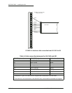
The connection between the 957/958/6000i and the 491 requires the
10-foot (3-meter) data cable supplied with the 491. The cable connects to
the AUX port on the back of the navigator.
The cable is shipped with the connector installed — the following infor-
mation is provided for cases where it is necessary to remove and reinstall
the connector.
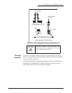
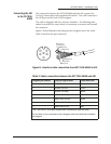
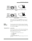
Figure 9 below illustrates the wiring for the navigator end of the cable.
Table 5 describes the pin’s functions.
Figure 9: Interface cable connection from 957/958/6000i to 491
Brown (pin 1)
Green (pin 1)
White (pin 2)
Blue (pin 6)
Orange (pin 5)
Violet (pin 4)
Black (pin 3)
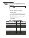
Table 5: Cable connection between the 957/958/6000i and 491
navigator pin number AUX port signal name Cable wire color
1* Shield/Gnd Brown
1* Remote On Gnd Green
2 Remote On input White
3 NMEA AUX In (B) Black
4 NMEA AUX Out (A) Violet
5 NMEA AUX Out (B) Orange
6 NMEA AUX In (A) Blue
* Pin 1 on the 957 AUX port requires two connections from the cable.
The red wire is not connected on the navigator end, and should be insulated
and capped.