


CLASSIFICATION
Einstufung
No.
DS-Eval4570-2400
REV.
C
SUBJECT
Thema
EvalBoard PAN4570
PAGE
Seite
10 of 20
CUSTOMER’S CODE
EvalPAN4570
PANASONIC’S CODE
DATE
Datum
06.11.2006
European Technology Center
Panasonic Electronic Devices (EUROPE) GmbH
APPROVED
genehmigt
CHECKED
geprüft
DESIGNED
Erstellt
8.3. SELECTING THE HARDWARE PLATFORM
The EmberZNet stack uses a Ember
TM
platform (Ember
TM
breakout board and RCM
module), which is defined in a BOARD_HEADER file. This file is named dev0455.h and
located in the folder
….\Ember\EmberZNet2.5.0\hal\micro\xap2b\em250\board\
IMPORTANT: Because the use and settings of GPIOs on the PAN4570 testboard is
different another BOARD_HEADER file is required.
After installation of EmberZNet2.5.0 the required change of the BOARD_HEADER file
can be done as follows:
Rename the dev0455.h extracted with EmberZNet for example in dev0455_ember.h
Copy the PAN4570.h file from the cd to the location where dev0455.h was located
Rename the PAN4570.h file to dev0455.h
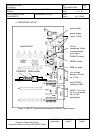
PAN4570.h enables D11, D14, SW2 and SW6 connected to PAN4570 for the use of
the “simple-lighting” sample application.
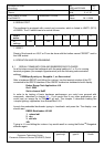
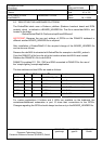
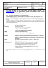
The two switches and two LEDs are used as follows:
board LED GPIO
Ember
TM
name
function
LIGHT D11 3 HEARTBEAT_LED heartbeat
LIGHT D14 12 LIGHT LIGHT
LIGHT SW2 15 BUTTON 1 LIGHT ON and networking
LIGHT SW6 8 BUTTON 0 LIGHT OFF and networking
SWITCH SW2 15 BUTTON 1 LIGHT ON
SWITCH SW6 8 BUTTON 0 LIGHT OFF
(Table 4)
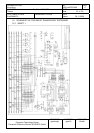
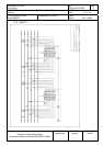
For custom applications 5 buttons and 4 LEDs are available on the testboard, the
carrierboard/testboard schematics in part 10 show their connections to the GPIOs.
Changes regarding the GPIOs should always be done only in the BOARD_HEADER file.