


CLASSIFICATION
Einstufung
No.
DS-Eval4570-2400
REV.
C
SUBJECT
Thema
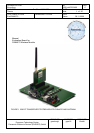
EvalBoard PAN4570
PAGE
Seite
7 of 20
CUSTOMER’S CODE
EvalPAN4570
PANASONIC’S CODE
DATE
Datum
06.11.2006
European Technology Center
Panasonic Electronic Devices (EUROPE) GmbH
APPROVED
genehmigt
CHECKED
geprüft
DESIGNED
Erstellt
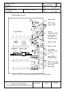
For use of the P2 2mm contacts the black socket P2-X1 is the negative/ground contact
and the red socket P2-X2 is the positive terminal.
A linear regulator on the testboard regulates the input voltage down to the +5V DC board
supply. A second linear regulator regulates the +5V DC down to the module VCC supply
of 2,1/2,7/3,4Vdc.
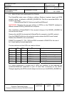
5.2. D.C. POWER FROM A USB DEVICE:
In case no dedicated supply is available, DC supply can be taken from an USB
connection. The +5V DC from the USB feeds the linear regulator for the modules VCC
supply of 2,1/2,7/3,4Vdc (see Table 1).
Please note that communication via the USB connector is not possible.
Please take into account that when using the +5V DC feed to the 34-pin-headers in
combination with USB power supply the voltage is not +5V but unregulated 4.3 V DC due
to the voltage drop at a protection diode connected in series on the testboard.
Warning: Do not overload the USB power source. Check for the current available from
your USB device in order to avoid malfunction of or damage to your USB power source.
5.3. POWER ON
Set SW7 to the position 1 = on. (With power from USB position 1 is off and position 2 is
on). D7 should be lit indicating that +5Vdc supply is available on the testboard. D8 should
be lit indicating that the regulated Vcc module supply is available.
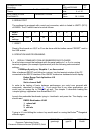
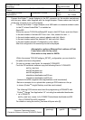
The dc regulator output voltage is set with a jumper on JP3 or JP4 as follows:
jumper on
2-pin header
regulator output
voltage VCC
remarks
JP4 only (default) 2,7 Vdc typical for PAN4570
no jumpers 3,4 Vdc
Maximum
for PAN4570
JP3 only 2,1 Vdc
Minimum
for PAN4570
(Table 2)