


CLASSIFICATION
Einstufung
No.
DS-Eval4570-2400
REV.
C
SUBJECT
Thema
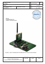
EvalBoard PAN4570
PAGE
Seite
4 of 20
CUSTOMER’S CODE
EvalPAN4570
PANASONIC’S CODE
DATE
Datum
06.11.2006
European Technology Center
Panasonic Electronic Devices (EUROPE) GmbH
APPROVED
genehmigt
CHECKED
geprüft
DESIGNED
Erstellt
Important: To install and run the programs you need Administrator rights on the test PC.
Check for software updates at www.Ember.com
.
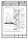
2. SETTING UP THE EVALBOARD
Plug a PAN4570 Carrierboard on one of the three 34-pins headers (B or C or D) as
shown in Figures 1 and 2. Please take care that pin 1 of the Carrierboard connects to
pin1 of the testboard according to the “1” marking on the PCBs.
Important: Only 1 PAN4570 carrierboard may be plugged on the testboard.
The other 34-pin headers/sockets are provided for demo application boards like sensors,
actuators, etc. On slot A a socket is mounted instead of double pin rows for applications
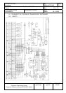
using a plug with pins. For details on the testboard see chapter 3 and the testboard
schematic in chapter 10.
Mount the 50Ohms 2,4GHz antenna with SMA male plug on the PAN4570 carrierboard
SMA socket.
Check if a Vcc=+2,7Vdc module supply jumper is set to the corresponding 2-pin header
(B or C or D).
Remark: Instead of a jumper an amperemeter for measuring the module current on VCC
can be connected to the module supply 2-pin header. In this case the voltage drop at the
amperemeters internal resistor reduces the Vcc voltage applied to PAN4570 depending
on the current drawn. Therefore check if the amperemeter used has an internal
resistance of sufficiently low value.
As an option a +5Vdc regulated voltage is available on the 34-pins headers (this does not
apply to usage of USB as power supply).
Important: Do not connect the +5Vdc directly to PAN4570 because it may damage the
Module.
The reason for the +5Vdc option are applications needing a higher supply voltage (i.e.
with white LEDs). In order to use +5Vdc on the headers it has to be connected by
plugging a jumper to position JP2.
The total available current from Vcc plus the current from +5Vdc is approximately 270mA
maximum, provided that the power source voltage applied to P1-P2-P3 does not drop
below approximately 6,6Vdc.
For the location of switches and jumpers on the Evaluation board see chapter 3
.