


C2473M-C (8/06) 7
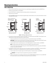
POLE MOUNTING
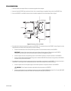
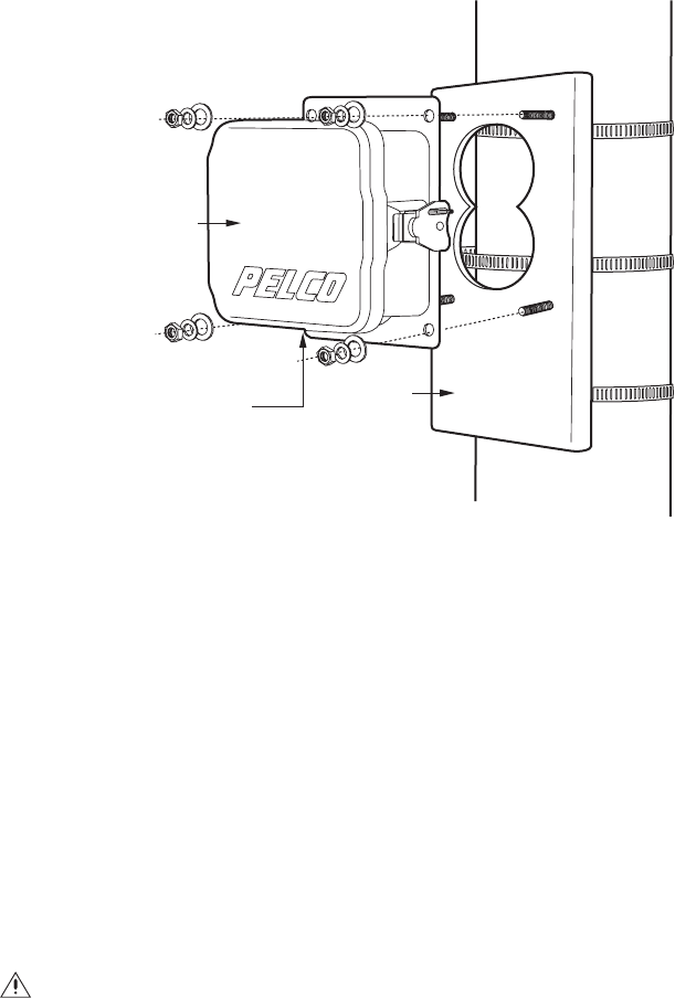
1. Install the PA402 mount adapter. Refer to the instructions supplied with the adapter.
2. Open the lid of the IPS-RDPE-2 box. Install two 3/4-inch (1.91 cm) conduit fittings (not supplied). Close the lid of the IPS-RDPE-2 box.
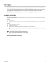
3. Attach the IPS-RDPE-2 to the PA402, and secure with the hardware supplied with the mount adapter. Refer to Figure 2.
Figure 2. Mounting to Pole with PA402
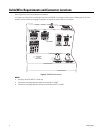
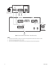
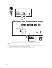
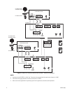
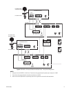
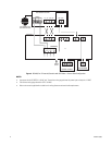
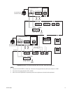
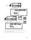
4. Run conduit with wiring from the positioning system to the IPS-RDPE-2. To connect the wires to the IPS-RDPE-2, refer to Figure 3 or to the
label attached to the inside lid of the data port box, and do the following:
a. Connect the communication wires from the positioning system to the communication connector of the IPS-RDPE-2.
IMPORTANT: Connect all four communication wires from the Spectra III dome system or ExSite system to the IPS-RDPE-2.
Transmission and receive wires must be connected to perform software and language file uploads.
b. Connect the power wires from the positioning system to the 24 VAC OUT positions on the power connector of the IPS-RDPE-2.
c. Connect the video wires/cable from the positioning system to either the BNC VIDEO IN connector (if using coaxial) or UTP VIDEO IN
connector (if using UTP) of the IPS-RDPE-2.
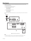
5. Run conduit with wiring from the power supply and wiring from the controller at the head-end to the IPS-RDPE-2. To connect the wires to
the IPS-RDPE-2, refer to Figure 3 or to the label attached to the inside lid of the data port box, and do the following:
a. Connect the power wires from the power supply to the 24 VAC IN positions on the power connector of the IPS-RDPE-2.
b. Connect the wires/cable from the controller at the head-end to either the FROM CONTROLLER connector (D or P control), BNC VIDEO
OUT connector (Coaxitron control) or UTP VIDEO OUT connector (UTP control) of the IPS-RDPE-2.
WARNING: Turn off power to the power supply before wiring the power to the IPS-RDPE-2
IPS-RDPE-2
PA402
CONDUIT
FITTINGS