


nicks, scratches, or corrosion at the top of the cone can allow air to pass, which could result in
creeping hose pressures. Polish out the defects using a fine abrasive polishing stick. When
polishing, apply a
light pressure to prevent excessive wear on the cone. You do not need to polish
the rough outer edge of the cone; this is not a sealing surface. Use compressed air to blow away
any dust created by the polishing process.
5.3 ASSEMBLY OF FIRST STAGE
1 Kit # 4000-4 is the Annual Service Kit for the SRB3600 Maximus. This kit contains the minimum
parts to be replaced at every annual service interval.
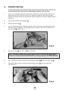
2. Before installing new O-rings on the piston and moving orifice, lubricate the O-rings with one of
the recommended lubricants
(see Section 7.3). Installing the small O-ring on the piston will
be easier if you use the brass-colored Sherwood O-ring installation cone (p/n TL106). Place the
cone over the tip of the piston. Slide the lubricated O-ring over the cone until it slips into the
piston groove.
3. Place the new piston seat on a clean piece of paper on a hard flat surface. Press the piston
tip firmly over the seat until it is fully installed. The piston is now rebuilt and ready for installation.
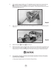
4. Use the Sherwood installation cones to prevent damage to the new O-rings during installation
onto the moving orifice. Use the black O-ring installation cone (p/n 29-TL108) to install first the
new O-ring and then the used backup washer onto the wider groove on the moving
orifice. Position them so that the black O-ring is closest to the wide end of the moving orifice.
Use the green O-ring installation cone (p/n 38-TL107) to install the O-ring into the groove
closest to the pointed tip of the orifice.
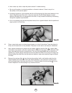
5. Using a greased soft probe,
lightly lubricate the first 1/8" of the small bore in the body
where the small piston and moving orifice O-rings seal.
6. With your finger, push the moving orifice assembly, pointed orifice end first, into the yoke end
of the main body as far as possible. Place the inlet filter into the main body on top of
the moving orifice. Place the new star washer from the service kiton top of the filter screen.
7. Replace the lightly lubricated O-ring onto the pressure adjusting ring . Lightly lubricate the
piston bore in the pressure adjusting ring on the surface where the large piston O-ring will seal.
8. Place the main spring over the piston stem. Insert the main spring and piston (with its clean,
lubricated new O-rings and seat) into the pressure adjusting ring.
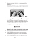
9. Screw the cap onto the pressure adjusting ring. Use a 15" adjustable wrench and bench
vise to
snugly tighten the cap to the pressure adjusting ring (see Photo # 4). Do not
overtighten.
10. Replace the lightly lubricated O-ring onto the main body. Be sure to place the O-ring into
the groove right next to the threads, not in the groove away from contact with the threads.
Lightly lubricate the bore in the pressure adjusting ring where the body O-ring will seal. With
10
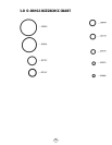
NOTE: Replace domed screen P/N 3601-16 with filter P/N 1390-7. Some first stage bodies have a groove
machined in the inlet for a filter retaining ring P/N J2790056B. For first stage bodies without the groove use
a star washer P/N 3504-6
22
23
7
6
15
3
2
20
19
21
26
18
18