


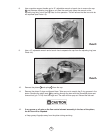

16. If you need to replace certain parts of the lever assembly (stem, spring, lever, etc.), you can do
this by temporarily screwing the orifice housing with the orifice back onto the lever
support and assembly (without the plastic case). With these parts screwed together, the locking
nut can be removed without all of the components springing apart. Remove the old part,
install the new part, and re-tighten the locking nut .
17. Hold the orifice housing in one hand. Temporarily install the adjusting knob and use it to
turn the orifice clockwise until it comes out of the orifice housing. Remove and discard the
O-rings on the orifice and the orifice housing .
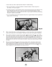
18. Grasp the oval exhaust valve with your fingers and pull first one and then the other locking
nipple out of the case.
19. Rinse all plastic and silicone parts in clean fresh water, and then blow the parts dry with
compressed air.
20. Inspect the case for any cracks. Look particularly closely at the area where the orifice
housing and the lever support clamp down. Replace the case if you find any cracks.
Squeeze
marks and lines caused by compression of the case between the lever support and
orifice housing are not a reason for changing the case.
21. Inspect the exhaust valve and the diaphragm for any tears or pin holes by stretching them
gently as you hold them up to a light. If you are repeatedly tearing diaphragms while
inspecting, you are applying too much force.
22. Inspect the orifice for any nicks, scratches, or corrosion. Polish out any corrosion or minor
scratches using a fine-grit rubberized polishing stick or a clean new pencil eraser. Remember
not to apply too much pressure when rotating the polishing stick. Check frequently to see when
the corrosion or scratch is gone and stop at that point. Blow all dust and debris out of the
orifice housing using clean compressed air.
23. Inspect all O-ring grooves in the metal parts of the second stage. Clean all O-ring grooves with
a lint-free cloth.
6.3 ASSEMBLY OF SECOND STAGE
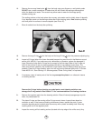
1 Install the exhaust valve into the case by inserting the two nipples into the small holes from
the outside of the case. Reach inside the case and pull each nipple firmly with the fingers until
you hear or feel it "click" into place. Inspect the exhaust valve to see that it is properly seated.
2. Install the lever support and assembly into the case, setting it firmly between the guide ribs
in the case.
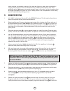
3. Lubricate and install new O-rings from the annual service kit onto the orifice Install
the orifice back into the orifice housing using your fingertip. Use the ad usting knob to
turn the orifice counter-clockwise until it stops.
4. Apply a drop of mild thread locker (such as Locktite 242
®
or equivalent) to the threads of the
lever support .
15
NOTE: Prior to this point, you should have cleaned and inspected all parts, following proper service
procedures. Do not continue until this has been done.
13
10
29
29
13
8
9
11
12
16
17
10
16
26
8 9
13
26
10
4
29