


Installation
20221586B 53
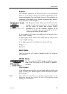
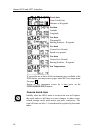
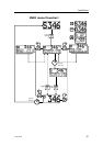
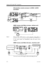
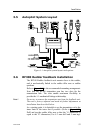
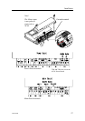
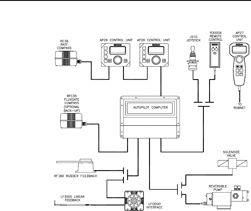
3.5 Autopilot System Layout
STBY
PWR
AUTO
SPEED
SETUP
NAV
TURN
pfjo^a=oPMMMu
STBY AUTO
WIND
SETUP
DODGE
INFO
STBY
PWR
AUTO
NAV
WIND
SETUP
DODGE
INFO
AUTO
NAV
STBY
PWR
Figure 3-1 Autopilot system layout with options
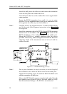
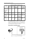
3.6 RF300 Rudder feedback installation
The RF300 Rudder feedback unit mounts close to the rudder,
and is mechanically linked to the rudder tiller arm or rudder
quadrant.
Refer to Figure 3-2 for the recommended mounting arrangement.
Note that the RF300 transmitter arm has two slots for the
transmission link. The slots enable maximum flexibility to
provide the 1:1 mechanical linkage relationship.
Note ! Do not try to remove the transmitter arm from the feedback unit.
The unit is factory adjusted and need no further adjustment at
installation than described below.
As a starting point, it is desirable to set the transmitter rod to the
inner limit of the outer slot if possible. (Refer to Figure 3-2).
Drill and tap the rudder tiller arm so that the Y1 dimension is
equal to the Y2 dimension (Use 4.2 mm drill and 5 mm tap).