


Installation
20221586B 55
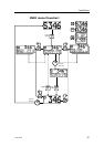
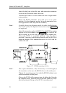
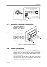
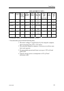
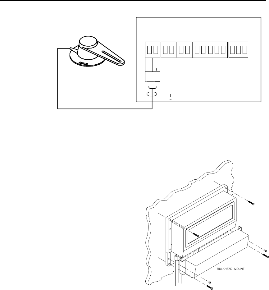
AUTOPILOT COMPUTER
MAIN PCB
Rudder
Feedb.
*
* NON POLARIZED
(COLOR INDEPENDENT)
RF +
RF
Figure 3-3 RF300 connection
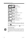
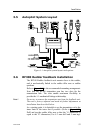
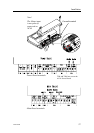
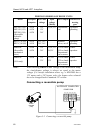
3.7 Autopilot computer installation
The autopilot computer is
designed to operate in a
location that provides
ambient temperatures
below +55°C (+130°F).
Note ! The autopilot computer
units (AC10, AC20 and
AC40) are not
weatherproof and should
be mounted vertically as
shown in a dry place
between the control unit
and the drive unit.
Figure 3-4 Autopilot computer mounting
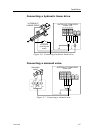
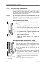
3.8 Cable connections
Use only shielded cables. This includes Mains input, drive units
and if necessary for the extension of the RF300 Rudder
Feedback cable. The clutch/bypass cable and the solenoid cable
should be 1,5 mm
2
(AWG14). Signal cables should be 0.5 mm
2
(AWG20) twisted pairs.
The mains supply cable and the drive unit motor cable should
have sufficient wire gauge. This will minimize voltage drop and
allow the drive unit to operate at full power.