


description/installation
h1000 pilot
Page 22
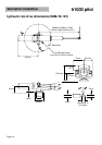
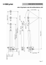
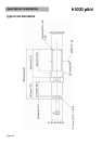
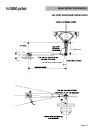
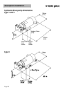
ram mounted parallel to vessel’s centre-line
key points on installation
x
Make sure that the rudder angle is limited by the rudder stops and not the limit of travel of the
ram arm. Failure to comply will damage the unit and invalidate the warranty.
x
Make sure that there is sufficient space at each end for the ram arm to extend fully. The ram
stroke length is given in the tables on Page 13 of this manual.
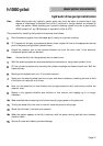
x
Check for full movement and security of the steering gear before applying any power to the
autopilot system. Refer to the installation checklist in the calibration section of this handbook.
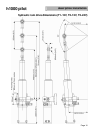
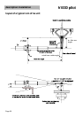
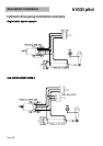
mounting a hydraulic linear ram on a vertical bulkhead
Due to the restricted movement of the ram mounting foot base (+14
q
/-10
q
for the Size 1 and 2 rams and
+
5
q
for the Size 3 ram), it is important that the maximum rudder angle is carefully measured and the
positioning of the ram, tiller arm length and offset are carefully followed from the diagrams on the
following page.
Caution: Failure to comply with these dimensions may cause premature failure of the ram and
place great stress on the structure of the vessel.
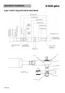
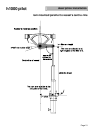
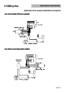
Note
: The Size 1 and 2 Linear Rams may be mounted in any orientation, without the need to fit an
external reservoir. The Size 3 Linear Rams requires an external reservoir which must be
positioned such that the reservoir is always higher than the drive unit at all normal angles of
heel.
Care must be taken to ensure that the connecting pipes are not in anyway kinked or turned
through any tight bends.