


h1000 pilot
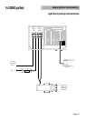
description/installation
Page 43
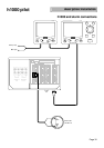
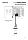
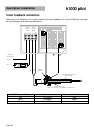
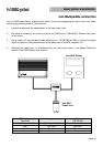
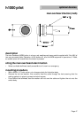
non-B&G paddle connection
Any non-B&G speed sensor used with this system must have a speed signal output from a hall-effect
device giving positive pulses of 12V maximum.
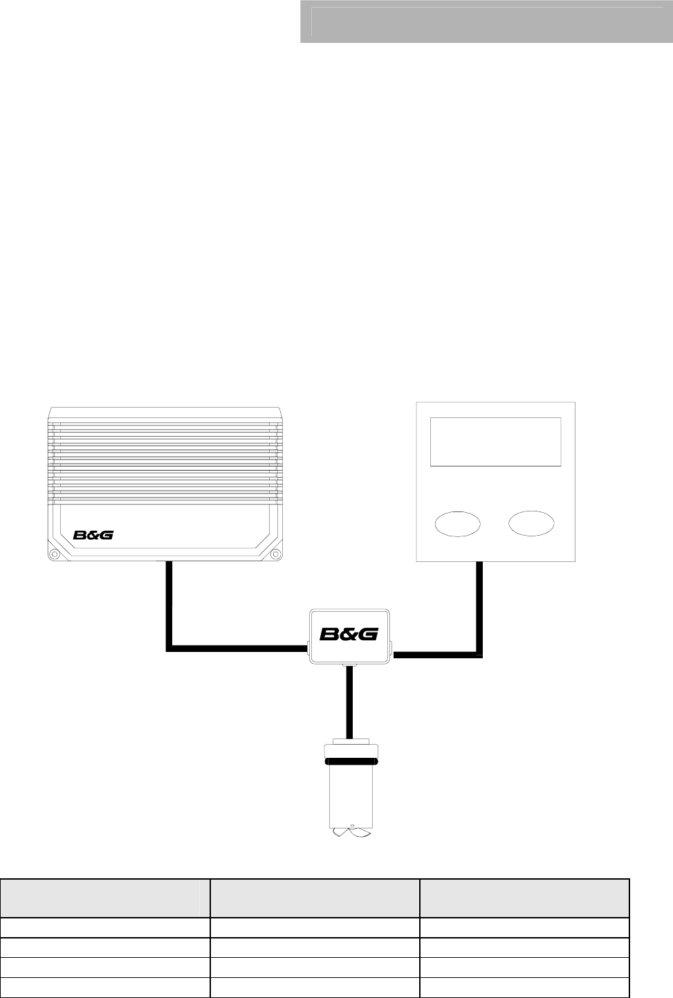
1. Locate the cable from the speed sensor to the instrument input.
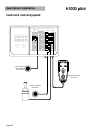
2. Cut cable (if necessary) and insert a junction box (B&G part no. 288-00-001). Connect like colour
to like colour.
3. Use a length of 2-core screened cable (B&G part no. 135-0B-098 9m/30ft) to connect the speed
signal and ground of the paddle sensor to the speed input of the ACP computer unit.
4. Calibrate the speed input in accordance with the instructions given in the Speed Calibration
section of the h1000 System User manual.
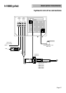
ACP Boat Speed
Terminals
Function Cable
135-0B-098
Green Speed signal input Red wire
Red Not used Not used
Black Ground Blue wire
Silver Screen Screen
Non B&G
Paddle Unit
Non B&G Display