


Chapter 5: Advanced Serverboard Setup
5-7
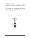
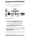
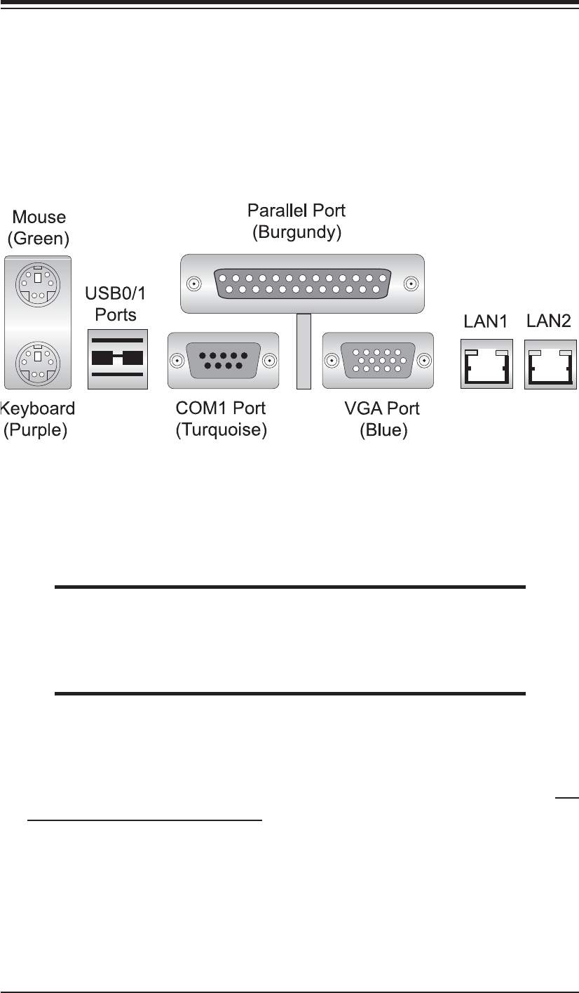
5-4 I/O Ports
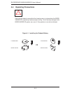
The I/O ports are color coded in conformance with the PC 99 specifi cation. See
Figure 5-2 below for the colors and locations of the various I/O ports.
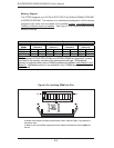
Figure 5-2. Rear Panel I/O Ports
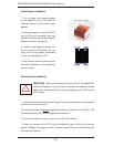
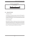
5-5 Installing Memory
Note: Check the Supermicro web site for recommended memory modules.
CAUTION
Exercise extreme care when installing or removing DIMM modules
to prevent any possible damage. Also note that the memory is inter-
leaved to improve performance (see step 1).
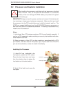
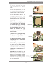
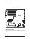
DIMM Installation (See Figure 5-5)
1. Insert the desired number of DIMMs into the memory slots, starting with
DIMM#1A and DIMM#2A and so on. The memory scheme is interleaved so you
must install two modules at a time, See the memory installation table on the next
page for the correct order in populating the DIMM slots.
2. Insert each DIMM module vertically into its slot. Pay attention to the notch along
the bottom of the module to prevent inserting the DIMM module incorrectly.
3. Gently press down on the DIMM module until it snaps into place in the slot.
Repeat for all modules (see step 1 above).