


Chapter 5: Advanced Serverboard Setup
5-5
5-3 Connecting Cables
Now that the processors are installed, the next step is to connect the cables to
the serverboard. These include the data (ribbon) cables for the peripherals and
control panel and the power cables.
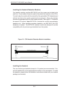
Connecting Data Cables
The ribbon cables used to transfer data from the peripheral devices have been
carefully routed in preconfi gured systems to prevent them from blocking the fl ow
of cooling air that moves through the system from front to back. If you need to
disconnect any of these cables, you should take care to reroute them as they
were originally after reconnecting them (make sure the red wires connect to the
pin 1 locations). If you are confi guring the system, keep the airfl ow in mind when
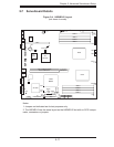
routing the cables. The following data cables (with their serverboard connector
locations noted) should be connected. See the serverboard layout diagram in this
chapter for connector locations.
Floppy Drive cable (JFDD1)
DVD-ROM Drive cable (IDE#1)
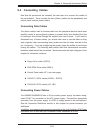
Control Panel cable (JF1, see next page)
1021M-T2: SATA cables (SATA0 ~ SATA3)
1021M-82: SCSI cables (JA1, JB1)
Connecting Power Cables
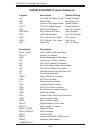
The H8DMR-i2/H8DMR-82 has a 20-pin primary power supply connector desig-
nated "JPW1" for connection to the ATX power supply. Connect the appropriate
connector from the power supply to JPW1 to supply power to the serverboard.
See the Connector Defi nitions section in this chapter for power connector pin
defi nitions.
In addition, your power supply must be connected to the 4-pin Auxiliary ATX Power
connection at J32 and the 8-pin Processor Power connector at JPW2.