


Chapter 5: Advanced Serverboard Setup
5-13
5-8 Connecting Cables
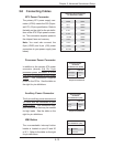
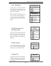
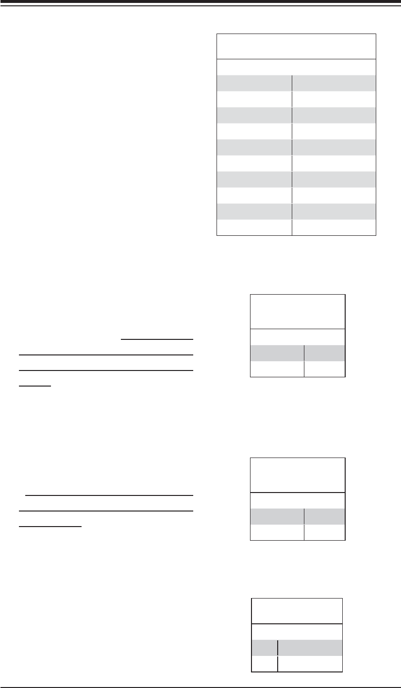
ATX Power Connector
The primary ATX power supply con-
nector (JPW1) meets the SSI (Super-
set ATX) 20-pin specifi cation. Refer to
the table on the right for the pin defi ni-
tions of the ATX 24-pin power connec-
tor. This connection supplies power to
the chipset, fans and memory.
Note: You must also connect the
8-pin (JPW2) and 4-pin (J32) power
connectors to your power supply (see
below).
Required Connection
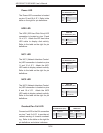
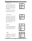
Processor Power Connector
In addition to the primary ATX power
connector (above), the 12v, 8-pin
processor power connector at JPW2
must also be connected to your power
supply. This connection supplies
power to the CPUs. See the table on
the right for pin defi nitions.
Processor Power
Connector
Pin Defi nitions (JPW2)
Pins Defi nition
1 through 4 Ground
5 through 8 +12V
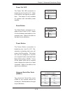
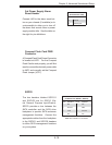
Auxiliary Power Connector
The 4-pin auxiliary power connector at
J32 must also be connected to your
power supply. This connection sup-
plies extra power that may be needed
for high loads. See the table on the
right for pin defi nitions.
Required Connection
Auxiliary Power
Connector
Pin Defi nitions (J32)
Pins Defi nition
1 & 2 Ground
3 & 4 +12V
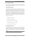
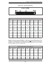
ATX Power 20-pin Connector
Pin Defi nitions (JPW1)
Pin# Defi nition Pin # Defi nition
11 GND8 1 GND1
12 +5V1 2 GND2
13 +5V2 3 GND3
14 3.3V1 4 GND4
15 3.3V2 5 GND5
16 +5V/SB 6 GND6
17 +12V4 7 GND7
18 +12V5 8 +12V1
19 +12V6 9 +12V2
20 Blcoked 10 +12V3
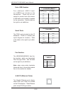
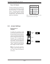
NMI Button
The non-maskable interrupt button
header is located on pins 19 and 20
of JF1. Refer to the table on the right
for pin defi nitions.
NMI Button
Pin Defi nitions (JF1)
Pin# Defi nition
19 Control
20 Ground