


Chapter 5: Advanced Serverboard Setup
5-9
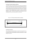
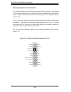
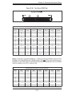
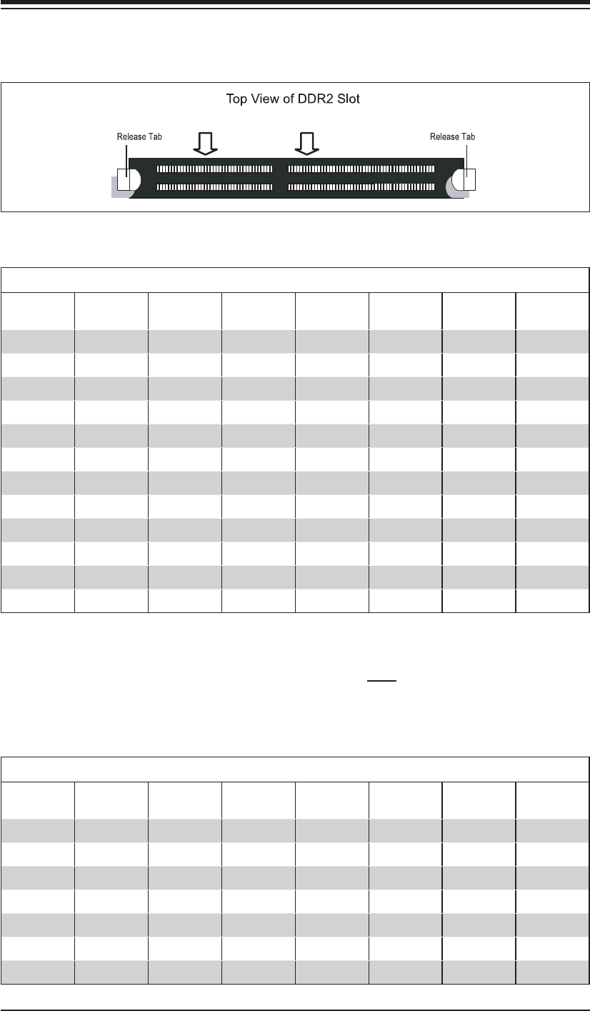
Figure 5-3b. Top View of DDR Slot
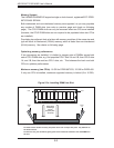
Populating Memory Banks for 128-bit Operation
CPU1
DIMM1A
CPU1
DIMM1B
CPU1
DIMM2A
CPU1
DIMM2B
CPU2
DIMM1A
CPU2
DIMM1B
CPU2
DIMM2A
CPU2
DIMM2B
XX
XX XX
XX XX
XX XXXX
XXXX
XXXXXX
XXXX XX
XXXXXXXX
XX
XXXX
XX XX
XXXXXX
Populating Memory Banks for 64-bit Operation
CPU1
DIMM1A
CPU1
DIMM1B
CPU1
DIMM2A
CPU1
DIMM2B
CPU2
DIMM1A
CPU2
DIMM1B
CPU2
DIMM2A
CPU2
DIMM2B
X
X
XX
XX
X X
XX
XX
Notes: X indicates a populated DIMM slot. If adding at least four DIMMs (with two CPUs
installed), the confi gurations with DIMMs spread over both CPUs (and not like the con-
fi guration in row 5) will result in optimized performance. Note that the fi rst two DIMMs
must be installed in the CPU1 memory slots.