


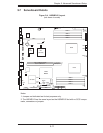
Chapter 5: Advanced Serverboard Setup
5-15
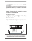
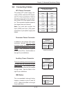
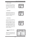
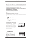
Power Fail LED
The Power Fail LED connection is
located on pins 5 and 6 of JF1. Refer
to the table on the right for pin defi ni-
tions. This feature is only available
for systems with redundant power
supplies.
Power Fail LED
Pin Defi nitions (JF1)
Pin# Defi nition
5 Vcc
6 Control
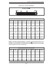
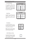
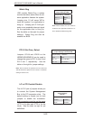
Reset Button
The Reset Button connection is lo-
cated on pins 3 and 4 of JF1. Attach
it to the hardware reset switch on the
computer case. Refer to the table on
the right for pin defi nitions.
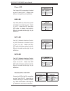
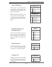
Power Button
The Power Button connection is
located on pins 1 and 2 of JF1. Mo-
mentarily contacting both pins will
power on/off the system. This button
can also be confi gured to function
as a suspend button (see the Power
Button Mode setting in BIOS). To turn
off the power when set to suspend
mode, depress the button for at least
4 seconds. Refer to the table on the
right for pin defi nitions.
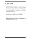
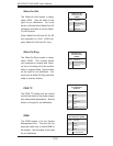
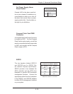
Universal Serial Bus Ports
(USB0/1)
Two Universal Serial Bus ports
(USB2.0) are located beside the
mouse port. See the table on the right
for pin defi nitions.
Reset Button
Pin Defi nitions (JF1)
Pin# Defi nition
3 Reset
4 Ground
Power Button
Pin Defi nitions (JF1)
Pin# Defi nition
1PW_ON
2 Ground
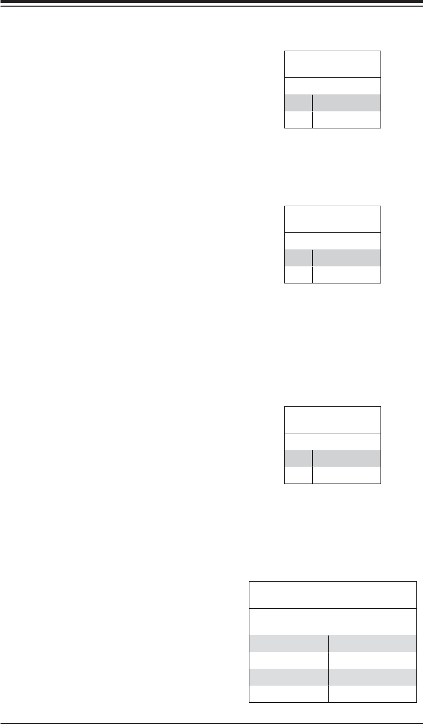
Universal Serial Bus Ports
Pin Defi nitions (USB0/1)
USB0
Pin # Defi nition
USB1
Pin # Defi nition
1 +5V 1 +5V
2 PO- 2 PO-
3 PO+ 3 PO+
4 Ground 4 Ground