Introduction
Teledyne Analytical Instruments 11
2.2.2 Gas Flow Control System
The Piping diagram is in the rear of this manual. A 10 port-switching
valve is used to control and direct gas flows to the FID detector. The
fixed volume sample loop ensures the same volume of sample injection
in the Analyzer every cycle.
2.2.3 Fuel and Blanket Air Systems
Stable flow is achieved by maintaining a constant pressure across
restrictors upstream from the cell. Each system incorporates an adjustable
pressure regulator, pressure gauge, and restrictor. A flame out light is
included to indicate when the flame fails. A fuel shut-off solenoid valve,
mounted on the line that supplies fuel, stops the fuel flow in case of flame
failure. This valve is located in line with the fuel port.
2.2.4 Flame Ionization Detection Cell
The carrier gas containing sample and fuel are combined within a tee
fitting located in the isothermal chamber. The mixed gas is emitted from
a burner within the sensor assembly. Blanket air is introduced into the
sensor (or cell) by means of a separate fitting that is located in the base
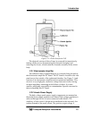
section of the assembly. The upper half of the assembly houses the
anode-igniter, collector, and flame guard thermistor.
2.3 Detection Cell
The upper section of the stainless steel flame ionization cell houses
the cylindrical collector electrode, the high voltage (+260 VDC) anode-
igniter coil, and the sensing thermistor of the flame guard circuit (see
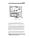
cell cross-section Figure 2-1).
WARNING: DANGEROUS HIGH VOLTAGE EXISTS AT THE
ANODE IGNITER COIL (+260 VDC). DO NOT
ATTEMPT TO DISCONNECT THE IGNITER COIL
CABLE OR DISASSEMBLE ANY OF THE FLAME
IONIZATION CELL COMPONENTS WITHOUT
TURNING OFF THE POWER AND DISCONNECTING
THE POWER CORD.
The collector is interconnected with the electrometer-amplifier PC
board by a coaxial cable. Although the cable and fittings are intended for
coaxial service, the cable is actually being used as a shielded single-
conductor connection.


