


Installation
Teledyne Analytical Instruments 17
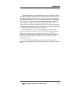
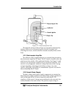
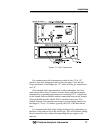
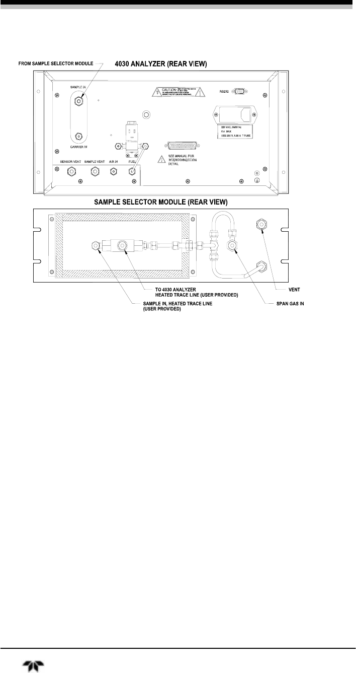
Figure 3-1: Gas Connections
Gas connections to the instrument are made at the 1/8”or 1/4”
stainless steel tube fittings provided on the rear panel. Note that the
Purge and Sensor Vent fittings are 1/4” while all other gas connections
are 1/8”.
If the Sample line is heat traced to avoid condensation, the User
must ensure that a clean (2 micron or better filter) and heated sample,
maintained at a constant temperature not exceeding 120 C, is delivered
to the Sample Selector Module and the connection between the Sample
Selector Module and the Model 4030 is similarly heat traced. The
Sample Selector Unit contains provisions to accept tubing diameter in
the range of 1.25 to 1.50 inches, typically the O.D. of the heat-traced
lines.
It is recommended that all gas tubing leading to the connections on
the back of the analyzer be of the coiled type. This will facilitate sliding
the unit out of the case without disconnecting the gas supply to the
analyzer.