Installation
Teledyne Analytical Instruments 16
Regardless of configuration, the analyzer/system must be installed
on a level surface with sufficient space allocated on either side for
personnel and test equipment access. Subject to the foregoing, the
Analyzer/system should be placed as close to the sample point as is
possible.
All pertinent dimensions, connecting points, and piping details can
be found in the drawings section as part of the outline, input-output, and
piping diagrams. These drawings are specific to the instrument or
system to which the manual applies.
3.3 User Connections
All user connections are made on the rear panel. Consult the input-
output and outline diagrams in the drawing section of the manual. Not
all the features displayed may be present in your system. Refer to any
Addenda for additional information that may apply to your instrument.
3.3.1 Electrical Power Connections
The standard analyzer requires a supply of 100-125VAC, single-
phase power. Power connections are made at the rear panel of the unit.
Refer to the input-output diagram for more information. The electrical
power service must include a high-quality ground wire. A high-quality
ground wire is a wire that has zero potential difference when measured
to the power line neutral. If you have the 220 VAC option, you will
require 220 or 240 VAC, 50/60 Hz power. Check the analyzer input-
output diagram, power schematic, outline, and wiring diagrams for
incoming power specifications and connecting points.
CAUTION: PRIMARY POWER TO THE SYSTEM SHOULD NOT
BE SUPPLIED UNTIL ALL CUSTOMERS WIRING IS
INSPECTED PROPERLY BY START-UP PERSONNEL.
3.3.2 Gas Connections
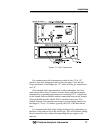
The analyzer gas connection diagram identifies the various gas
connection points as to function and location. Figure 3-1 shows the gas
connection points for Model 4030 and SAMPLE SELECTOR
MODULE (optional).


