


54
51
50
49
48
46
60
61
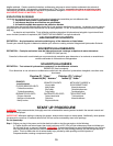
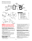
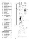
Figure 3B
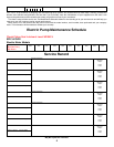
15
For 230 V
olt Units:
ITEM NO PART NO DESCRIPTION QTY
46 761-725 Power Cord 1
48 770-593 On/Off Plate 1
49 765-083 Toggle Switch 1
50 765-072 Wire 3
51 770-311 Fuse 8 Amp 2
54 765-050 Motor Starter 1
313-098 Earth Symbol Label 1
60 765-087 Lock Nut 1
61 765-089 Fuse Block Assembly 1
(See page 18,19 & 20 for additional and related diagrams.)
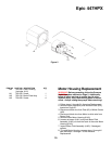
WARNING: Before proceeding, follow the Pressure
Relief Procedure outlined on Page 5. Additionally,
follow all other warnings to reduce the risk of an
injection injury, injury from moving parts or electric
shock. Always unplug the sprayer before servicing!
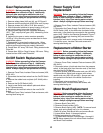
On/Off Switch Replacement
1. Remove Cover Plate, Insulator Plate and screws (#56,
#55 & #21). See pg. 20.
2.
Disconnect the four wires from the On/Off Switch (#49).
3. Remove the rubber boot and plate (#47 & #48) with a
wrench.
4. Remove the On/Off Switch (#49).
5. Install a new Switch and reattach plate and rubber
boot. Tighten securely.
6. Reconnect the four wires to the new On/Off Switch.
7. Reinstall Switch Cover Plate, Insulator Plate and
screws, with warning label facing out.
Power Supply Cord
Replacement
1. Remove Cover Plate, Insulator Plate and screws (#55,
#56 & #21). See pg. 20.
2. Disconnect the Power Supply Cord (#46) from; a) the
Fuse Holders on #61, and, b) the green wire
connected to the grounding screw (#42). Refer to the
Electrical Schematic, Figure 3A.
3. Loosen the cord grip housing (#45) and remove the
power cord (#46).
4. Install the new cord in reverse order of disassembly.
5. Install the cover, Insulator Plate and screws with
warning label facing out.
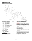
Replacement of Motor Starter
1. Remove Cover Plate, Insulator Plate and screws (#55,
#56 & #21). See pg. 20.
2. Disconnect wires, a) the red wire from the pressure
switch, b) the black wire from the motor and, c) the
black wire from the On/Off Switch.
3. Remove screws (#58) and washer and nuts (#52 #53).
4. Replace Motor Starter and re-secure with screws,
washer and nuts (#58, #53 and #52). Always use heat
sink material on the back of the Motor Starter when
installing.
5. Reconnect wires according to Figure 3A.
6. Reinstall cover, Insulator Plate and screws, with
warning label facing out.
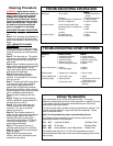
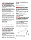
NEUTRAL
(BLUE)
FUSES
LINE
(BROWN)
GROUND
(YELLOW-GREEN)
POWER
SWITCH
PRESSURE
SWITCH
MOTOR
240V 50.0 A
SOLID STATE
RELAY
1
2
3
4
NC
Electrical Schematic for 230 Volt Motors
230V Service Instructions
Figure 3A
47
45
52
53
42
58