


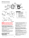

Pressure Switch Replacement
WARNING: Before proceeding, follow the Pressure
Relief Procedure outlined on Page 5. Additionally,
follow all other warnings to reduce the risk of an
injection injury, injury from moving parts or electric
shock. Always unplug the sprayer before servicing!
1. Remove outlet mounting bolt (#263) with a 5/8" open end
wrench and screws (#272) with a 3/16" allen wrench, from
the bottom of pump.
2. Remove the Filter Block Assembly (#294) from pump.
3. Remove Pressure Switch Screw (#27) and slide
Pressure Switch Knob (#28) off. (See Figure 6 on page 20.)
4. Remove Cover Plate (#56), then disconnect the two red
wires from posts 1 and 3 on Motor Starter.
5. Remove Screw (#27) Insert a 1/8" allen wrench into
screw opening and loosen Set Screw (#57) by turning
wrench counterclockwise, until clear of Pressure Switch
Cylinder. See pg. 20.
6. Carefully slide Switch Assembly (#290) down through the
bottom of pump, feeding the wires as you go. Be careful
not to damage wires.
7. Insert new Switch Assembly into housing while carefully
working the wires into the Switch Box. Using needle nose
pliers, reconnect the wires.
8. Making sure that the Switch Assembly is fully inserted,
tighten set screw (#57) with a 1/8" allen wrench until the
Switch Assembly is secure. Then install screw #27. See
pg. 20.
9. Inspect O-Rings (#291 & #292) on Switch Assembly and
#268 on Outlet Manifold (#266). If properly in place, then
install Filter Housing Assembly to pump by lining up dowels
and fluid passageway. Secure with screws #272.
10. Install Cover Plate (#56) and reinstall Pressure Switch
Knob (#28). See pg. 20.
11. The Pressure Switch is Factory Calibrated so no
adjustment is required.
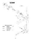
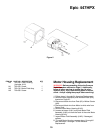
Service / Replacement of the
Pressure Prime Relief Valve
WARNING: Before proceeding, follow the Pressure
Relief Procedure outlined on Page 5. Additionally,
follow all other warnings to reduce the risk of an
injection injury, injury from moving parts or electric
shock. Always unplug the sprayer before servicing!
1. Remove the Groove Pin (#285) from Bypass Valve
Handle (#284). Push out Pin as shown in Figure 8.
2. Remove Handle (#284) and Bypass Cam (#283).
3. Using a wrench, loosen Bypass Housing (#277) and
unscrew. Inspect O-Rings #275 & #276.
4. Unscrew Bypass Valve Retainer (#282) and remove
Bypass Valve Stem (#279).
5. Inspect ball on end of Stem (#279) and seat, located in
the Bypass Housing (#277). Clean or replace if damaged.
Inspect O-Ring #278.
6. When reinstalling screw completed assembly into Filter
Block except for items #283, 284 and 285. Tighten securely
with wrench.
7. Install Bypass Cam (#283) over Bypass Retainer (#282),
lubricate with grease. Line up Cam (#283) with Filter Block
(#262).
8. Using Groove Pin, line up Stem (#279) with hole on
Handle (#284). Secure Handle with Groove Pin (#285).
9. IMPORTANT: If Handle (#284) rotates 360° check Pin on
Cam (#283).
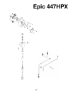
Service / Replacement
of Filter
WARNING: Before proceeding, follow the Pressure
Relief Procedure outlined on Page 5. Additionally,
follow all other warnings to reduce the risk of an
injection injury, injury from moving parts or electric
shock. Always unplug the sprayer before servicing!
PUMP FILTER
1. Unscrew Filter Housing (#288).
2. Unscrew Filter (#287) from Filter Block (#262), Left
Handed Thread, turn Filter (#287) clockwise to remove. If
Filter breaks off in Housing, use a small wood screw to
remove.
3. Inspect Seal (#289). Clean or replace.
4. Screw new or cleaned Filter in Filter Block. Turn
counterclockwise.
5. Reattach Filter Housing (#288).
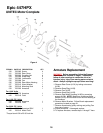
Gun Filter
WARNING: Follow all safety precautions as described
in high pressure warning section before proceeding.
If your spray gun leaks or spits at the tip when you
release the trigger, the needle or seat is dirty, worn or
damaged and must be cleaned or replaced.
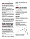
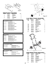
Replacement or Removal of Filter:
1. First pull down on trigger safety guard and swing away
from handle.
2. Unscrew handle from spray head.
3. Unscrew left hand threaded* filter from spray head.
(*NOTE: Left handed thread requires turning the filter
clockwise to remove.)
4. Screw new or cleaned (†) filter into the head. (To
reinstall left hand thread turn counterclockwise.)
5. Reattach handle to head and secure safety trigger guard.
(NOTE: If filter breaks off in the head use a small wood
screw to remove.)
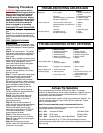
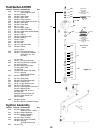
Figure 9 -- (†)For more detail, part number
information and assembly drawings at larger
scale, please see the LX-80 Professional
Airless Gun Owner's Manual (#313-012).
23