


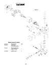
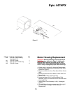

Gear Replacement
WARNING: Before proceeding, follow the Pressure
Relief Procedure outlined on Page 5. Additionally,
follow all other warnings to reduce the risk of an
injection injury, injury from moving parts or electric
shock. Always unplug the sprayer before servicing!
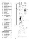
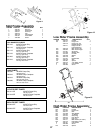
1. Remove safety plates (#43 and 44), pg. 22 Figure 6.
2. Remove outlet mounting bolt (#263) from rear of pump.
3. Remove screws (#41) with a 3/16" allen wrench
4. With fluid section attached to pump housing (# 40) pull
pump housing away from motor housing (#31).
5. Inspect gears beginning with crankshaft assembly
(#37). Then, output pinion gear (#33), followed by pinion
gear (#38).
6. Inspect pinion gear on motor armature assembly
(#139) pg. 18 by removing motor as described in motor
replacement section.
7. Reassemble by reversing the above order. When
reassembling, make sure that all washers are in place
and that gears and bearing are properly lubricated.
8. Grease Item #37 every 100 hours. Fitting located under
Plate #44.
9. Grease Item #300 on Page 24 every 100 hours. Fitting
located on Item #300 under Plate #44.
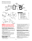
On/Off Switch Replacement
WARNING:
Before proceeding, follow the Pressure
Relief Procedure outlined on Page 5. Additionally,
follow all other warnings to reduce the risk of an
injection injury, injury from moving parts or electric
shock. Always unplug the sprayer before servicing!
1. Remove Cover Plate, Insulator Plate and screws (#56,
#55 & #21).
2. Disconnect the two black wires from the On/Off Switch
(#49).
3. Remove the rubber boot and plate (#47 & #48) with a
wrench.
4. Remove the On/Off Switch (#49).
5. Install a new Switch and reattach plate and rubber
boot. Tighten securely.
6. Reconnect the two black wires to the new On/Off
Switch.
7. Reinstall Cover Plate, Insulator Plate and screws, with
warning label facing out.
Power Supply Cord
Replacement
WARNING: Before proceeding, follow the Pressure
Relief Procedure outlined on Page 5. Additionally,
follow all other warnings to reduce the risk of an
injection injury, injury from moving parts or electric
shock. Always unplug the sprayer before servicing!
1. Remove Cover Plate, Insulator Plate and screws (#55,
#56 & #21).
2. Disconnect the Power Supply Cord (#46) from; a) the
On/Off Switch (#49), b) the white wire connected to the
motor and, c) the green wire connected to the grounding
screw (#42). Refer to the Electrical Schematic, Figure 7.
3. Loosen the cord grip housing (#45) and remove the
power cord (#46).
4. Install the new cord in reverse order of disassembly.
5. Install the cover, Insulator Plate and screws with
warning label facing out.
Replacement of Motor Starter
WARNING: Before proceeding, follow the Pressure
Relief Procedure outlined on Page 5. Additionally,
follow all other warnings to reduce the risk of an
injection injury, injury from moving parts or electric
shock. Always unplug the sprayer before servicing!
1. Remove Cover Plate, Insulator Plate and screws (#55,
#56 & #21).
2. Disconnect wires, a) both red wires from the pressure
switch, b) the black wire from the motor and, c) the black
wire from the On/Off Switch.
3. Remove screws (#58) and washer and nuts (#52 #53).
4. Replace Motor Starter and re-secure with screws,
washer and nuts (#58, #53 and #52). Always use heat
sink material on the back of the Motor Starter when
installing.
5. Reconnect wires according to Figure 7.
6. Reinstall cover, Insulator Plate and screws, with
warning label facing out.
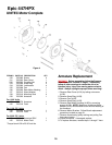
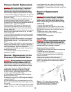
Motor Brush Replacement
WARNING: Before proceeding, follow the Pressure
Relief Procedure outlined on Page 5. Additionally,
follow all other warnings to reduce the risk of an
injection injury, injury from moving parts or electric
shock. Always unplug the sprayer before servicing!
1. Remove Brush Plate (#22).
2. Remover Brush Insulator (#23).
3. Remove Brush Spring (#25). NOTE: To remove brush
spring, push spring down and in for it to release.
4. Back off screw. Hold Brush Wire and remove Brush.
5. Inspect Motor Brush. If damaged replace.
6. Repeat procedure for other brush.
7. To install Motor Brushes, reverse steps 1 through 6,
NOTE: Never operate this unit without Brush Insulator
and Brush Plate installed.
21