


6 English
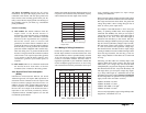
AC Output: The circuit breaker or fuse used must be
rated and approved for use on 120V AC branch circuits
for 120V models and for 230VAC branch circuits for
230V models. The wire size used between the Prosine
Inverter output and the breaker, and between the breaker
and your loads, must be sized to match the circuit
breaker’s rating, in accordance with the electrical codes
or regulations applicable to your installation. Refer to
Table 1 for sizing information.
Disconnect devices: Since circuit breakers can be
turned off and fuses can be removed from the circuit,
either type of device will also meet the requirement for
a disconnect device in each of the above circuits. Note
that the required disconnect device is not intended for
disconnection under load, it is only meant to be a way
to isolate the Prosine Inverter from the input and output
power sources.
2.4.2 Making AC Wiring Connections
Again, this section applies to those models configured
with an AC hardwire terminal strip. As mentioned
previously, your AC wiring must be sized to match the
current rating of the AC breakers you provide on the
input and output AC circuits in accordance with the
electrical codes or regulations applicable to your
installation. Table 1 is based on the U.S. National
Electrical Code (1999), the Canadian Electrical Code
(1998), and European wiring practices (for 230V
models). There may be other codes and regulations
applicable to your installation.
Note that there is no difference between the
recommendations for the 1000 and 1800 models. This
is because the bypass rating of these products is the
same (i.e. 15A for 1000 and 1800 and 10A for 1000i
and 1800i).
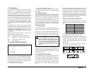
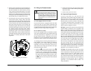
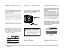
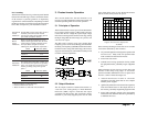
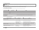
Figure 3 may be a useful reference as it illustrates the
AC wiring connection terminals for Prosine Inverter
models that are AC hardwire configured.
AC Wiring should be connected in the following order:
1. AC INPUT (source)
2. AC OUTPUT (load)
To make AC wiring connections:
1. The AC wiring compartment is located on the right-
hand side of the Prosine Inverter when looking at
the front of the unit. Remove the AC wiring
compartment cover to gain access to the AC terminal
strip inside.
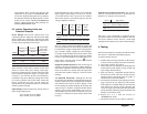
2. Remove the knockouts from the cover of the wiring
compartment to create holes for your cable clamps
(see Figure 3).
3. Run the three conductor AC INPUT (source) wiring
through a cable clamp and into the wiring
compartment, via the knockout on the right side of
the front panel. Connect the AC INPUT ground wire
first to the ground terminal (ground symbol with
circle around it), and then connect the AC INPUT
line and neutral wires to the corresponding Prosine
Inverter AC input terminals. Refer to Table 2 for
typical colour coding and terminal identification.
4. In a similar manner, connect the AC OUTPUT
(load) wiring to the Prosine Inverter AC output
terminals (connect the output ground to the ground
terminal identified by the symbol with no circle
around it). Terminal to wiring connections should
be done as shown in Table 2.
5. After wiring, double check and review all
connections to make sure the wires are in the correct
terminals and the terminals are tight (the
recommended torque is 7.5 in-lbs., 9.8 Nm).
Table 1. Circuit Breakers and Wire Sizing
Figure 3. AC wiring terminals (hardwire versions only)
WARNING
Shock Hazard. Before proceeding further,
ensure that the Prosine Inverter is NOT
connected to any batteries, and that all wiring
is disconnected from any electrical sources.
Do not connect the output terminals of the
inverter to an incoming AC source.
LEDOM
TUPTUOCAdnaTUPNICA
deriuqeR
gnitaRrekaerB
deriuqeR
eziSeriW
V42/21-0001
V42/21-0081
.xamA02GWA21
V42/21-i
0001
V42/21-i0081
.xamA01mm5.2-0.1
2
Table 2. AC Terminal and Wiring
Identification
LANIMRET
ROLOCERIWCA
CAV021
)naciremA.N(
CAV032
)naeporuE(
)L(ENILkcalBnworB
)N(LARTUENetihWeulB
DNUORG
roneerG
reppocerab
rowolleY/neerG
reppocerab
Xantrex Prosine Inverter Owner’s Manual