


English 7
AC Safety Grounding: During the AC wiring
installation, AC input and output ground wires are
connected to the inverter. The AC input ground wire
must connect to the incoming ground from your AC
utility source. The AC output ground wire should go to
the grounding point for your loads (e.g. a distribution
panel ground bus).
Neutral Grounding:
a) 120V models: The neutral conductor of the AC
output circuit of the Prosine Inverter is
automatically connected to the safety ground during
inverter operation. This conforms to National
Electrical Code requirements that separately
derived AC sources (such as inverters and
generators) have their neutral conductors tied to
ground in the same way that the neutral conductor
from the utility is tied to ground at the AC breaker
panel. For models configured with a transfer relay,
when AC utility power is present and the Prosine
Inverter is in bypass mode, this connection (neutral
of the inverter‘s AC output to input safety ground)
is not present so that the utility neutral is only
connected to ground at your breaker panel, as
required.
b) 230V models: There is no connection made inside
the Prosine Inverter from either of the line
conductors (line or neutral) to the safety ground.
2.4.3 Ground Fault Circuit Interrupters
(GFCIs)
Installations in Recreational Vehicles (for North
American approvals) will require GFCI protection of
all branch circuits connected to the AC output of the
hardwire terminal equipped Prosine Inverters. In
addition, electrical codes require GFCI protection of
certain receptacles in residential installations. While
the true sine wave output of the Prosine Inverter is
equivalent to the waveform provided by utilities,
compliance with UL standards requires us to test and
recommend specific GFCIs.
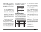
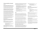
surge capability and frequent low input voltage
warnings and shutdowns.
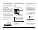
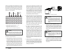
These low input voltage warnings are due to DC voltage
drop across the cables from the inverter to the batteries.
The longer and narrower these cables, the greater the
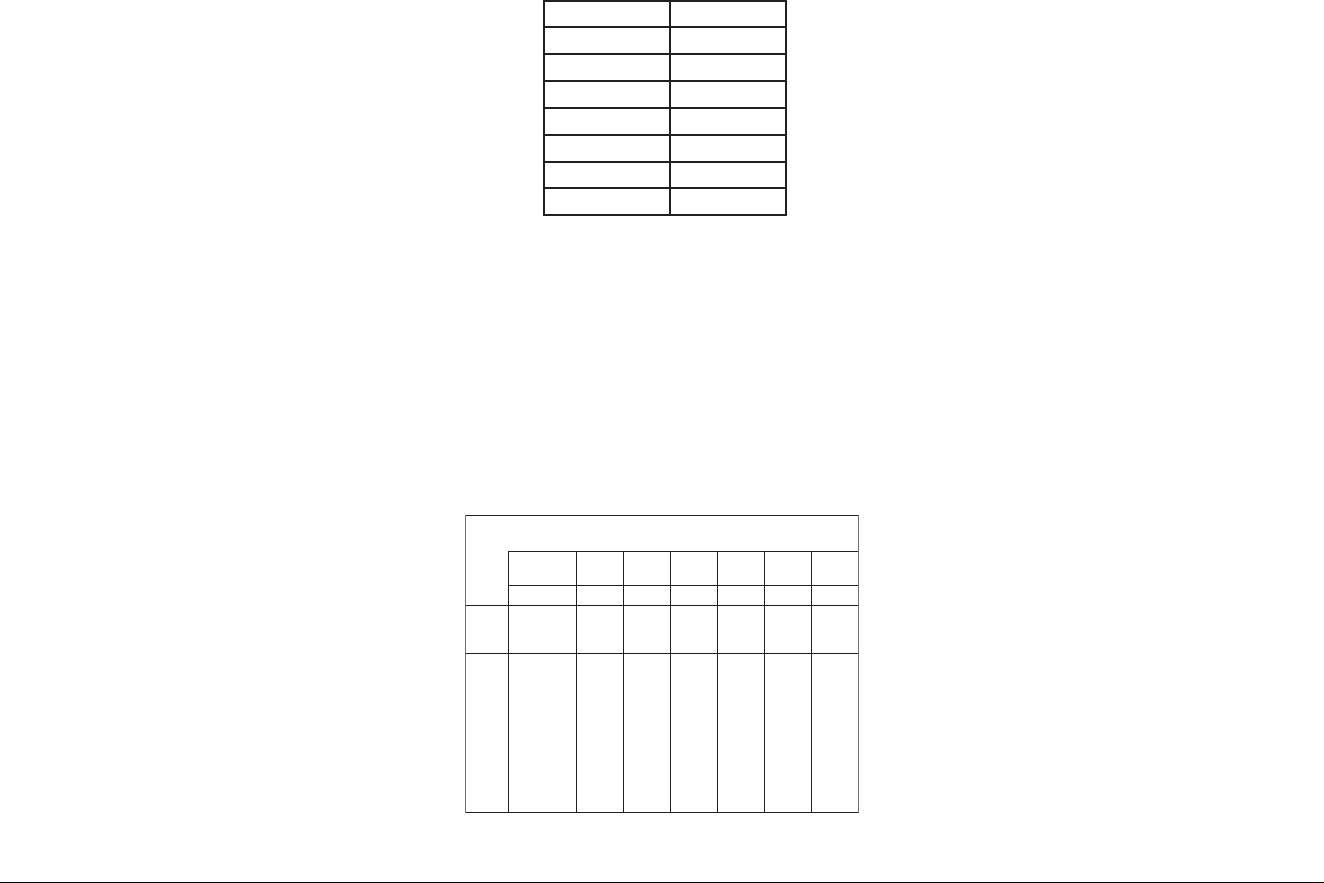
voltage drop. Table 3 shows voltage drop per foot of
cable, at various power output levels.
For example, if the 1800 Inverter is 10 ft. from your
battery, is operating at 2000 watts, and is improperly
connected with #4AWG wire, then you can expect a
voltage drop per foot of 0.0506 V. Total cable length is
actually 20 ft., not 10 ft., since the cable length is
measured from the battery to the inverter and back.
Therefore, multiply 0.0506 V by 20 to get a total voltage
drop of 1.012 V. If your battery voltage is only 11.2 VDC,
then the actual voltage at the inverter is 10.188 (11.2
V–1.012 V) because of this significant voltage drop.
The Prosine Inverter will either be in low input voltage
warning or shutdown in such a condition. In high current
draw and surge situations, the unit may go into low
input voltage shutdown if the cables are too small and
too long.
Increasing your DC cable size will help improve the
situation. With cables sized correctly, and using a #0
AWG cable, your voltage drop will be 0.02 VDC
(multiplied by 20, you get a total voltage drop of 0.4 VDC).
This illustrates that at 10 ft. away from the battery and
with large cables, you can expect voltage drop. Again,
try to keep cable length to a minimum and use the
maximum gauge cable possible. Xantrex recommends
the following cables for optimum inverter performance
(apply to both 120 V and 230 V versions).
1000/12: #0 AWG or 55 mm
2
1000/24: #6 AWG or 13 mm
2
1800/12: #4/0 AWG or 110 mm
2
1800/24: #2 AWG or 34 mm
2
Also, use only high quality copper wiring and keep cable
length short, a maximum of 3–6 ft.
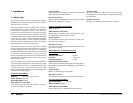
Xantrex has tested the following GFCI-protected 15 A
receptacles and found that they functioned properly
when connected to the AC output of the inverter:
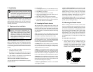
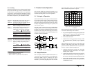
2.4.4 Making DC Wiring Connections
Follow this procedure to connect the battery cables to
the DC input terminals on the Prosine Inverter. Your
cables should be as short as possible (ideally, less than
10 ft./3 m) and large enough to handle the required
current, in accordance with the electrical codes or
regulations applicable to your installation. Cables that
are not an adequate gauge (too narrow) or are too long
will cause decreased inverter performance such as poor
Xantrex Prosine Inverter Owner’s Manual
RxI=V
ecnatsiseRxtnerruC=egatloV
retrevnI
)W(tuptuO
00500010051000200520003
)A(tnerruC05001051002052003
eriW
eguaG
)GWA(
ecnatsiseR
)tf/smho(
C°52@
egatloV
porD
.tfrep
egatloV
porD
.tfrep
egatloV
porD
.tfrep
egatloV
porD
.tfrep
egatloV
po
rD
.tfrep
egatloV
porD
.tfrep
0/4050000.05200.00500.05700.00010.05210.00510.0
0/3360000.02300.03600.05900.06210.08510.098
10.0
0/2970000.00400.09700.09110.08510.08910.07320.0
0001000.00500.00010.00510.00020.00520.00030.0
1621000.03600.06210.098
10.02520.05130.08730.0
2951000.00800.09510.09320.08130.08930.07740.0
3102000.01010.01020.02030.02040.03050.03060.0
4352000
.07210.03520.00830.06050.03360.09570.0
Table 3. Voltage drop per ft of DC cable
* With Line/Load inversion check & indicator light
**Hospital Grade
rerutcafunaMledoM
NOTIVEL107/9956
NOTIVEL*227/8956
ELGAEyrtneSkcohS
RUOMYES&SSAPNCW-1951
LLEBBUHAYG252FG
TNAYRBITF
25RFG
TNAYRB**ITF28RFG