


English 9
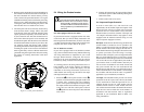
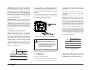
DC Grounding:
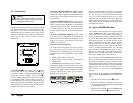
The Prosine Inverter has a lug on the rear panel labeled
Chassis Ground. This lug is used to connect the chassis
of the inverter to your DC ground as is required by
regulations for some installations. Depending on where
the Prosine Inverter is installed, follow the instructions
below that correspond to your installation location.
3. Prosine Inverter Operation
This section details how the unit functions as an
inverter, provides information on the control panel, and
describes operating limits for inverter operation.
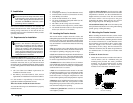
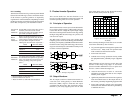
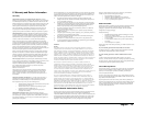
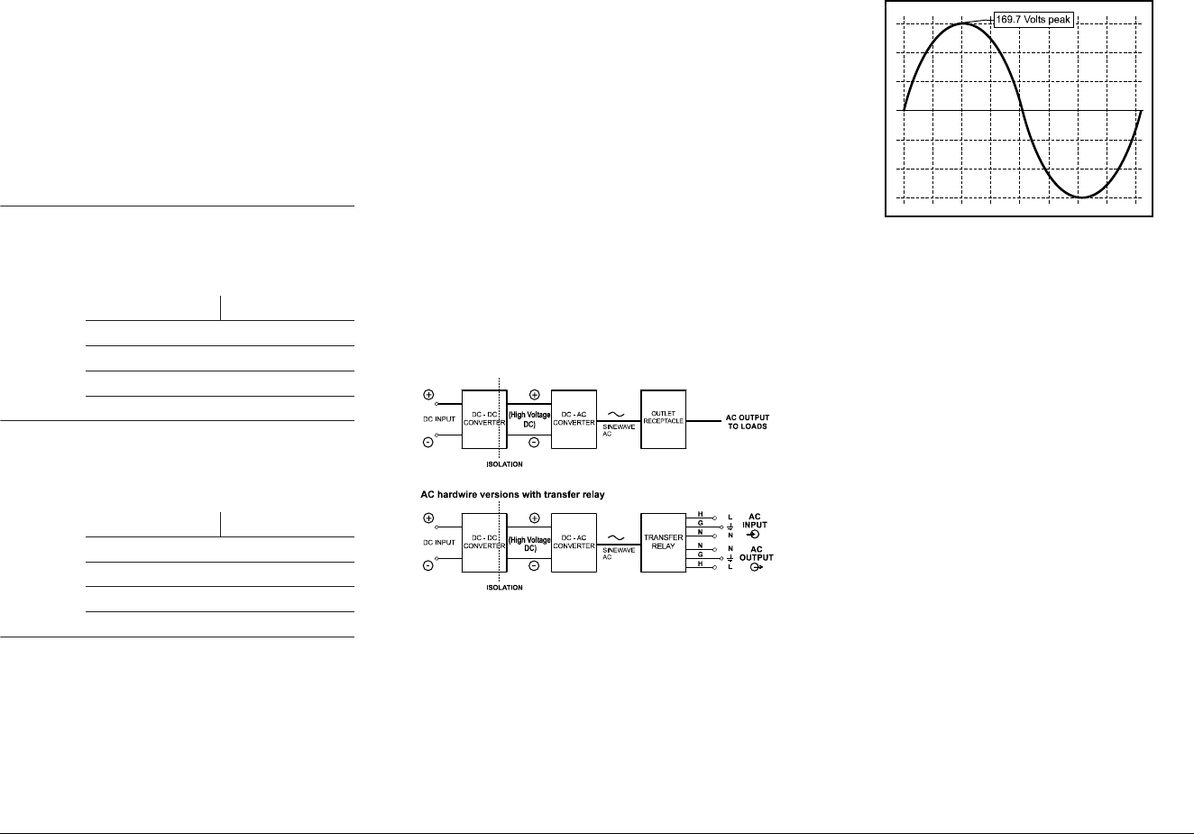
3.1 Principles of Operation
The Prosine Inverter converts power from the batteries
in two stages. The first stage is a DC-to-DC converter,
used to raise the low voltage DC input to high voltage
DC. The second stage is the actual inverter stage, taking
the high voltage DC and converting it to a precise, true
sine wave AC output.
The DC-to-DC converter stage uses modern high
frequency power conversion technology that eliminates
the bulky, low frequency (50/60 Hz) based transformers
found in inverters using older technology. The inverter
stage uses advanced power semiconductors that provide
excellent overload capabilities.
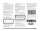
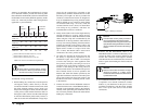
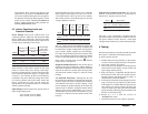
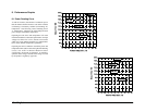
3.2 Output Waveform
The AC output waveform of the Prosine Inverter is a
“true sine wave” with typically 1% Total Harmonic
Distortion (THD). Figure 6 illustrates the output
waveform from the inverter. This waveform is nearly
identical to your utility-supplied power and in some
cases where utility power is poor, the Prosine Inverter
delivers cleaner, more precise AC power.
There are many advantages of true sine wave over other
wave forms delivered by other inverters:
• AC powered equipment is designed to operate with
true sine wave. Many loads will perform better
when connected to the Prosine Inverter.
• motor loads start easier
• reduced stress on surge protection circuitry within
the equipment means potentially longer equipment
life
Many advantages of true sine wave are also due to the
absence of the sharp-rising edges of waveforms
prevalent in either modified sine wave or square wave
inverters. Some of these advantages are:
• reduced interference in audio or electronic
equipment, especially those that use less complex
internal power supplies
• significantly reduced in-rush current into capacitive
loads and reduced stress on the output devices of
the inverter, potentially lengthening equipment life
• motor loads generally operate cooler and quieter
without the extra harmonic distortion generated by
a modified sine wave.
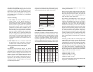
lanoitaerceR
elciheV
snoitallatsnI
fineerg(eriwreppocregralroGWA8#esU
sissahcehtottierucesdna)detalusni
ni
tniopgnidnuorgehtsallewsaguldnuorg
*.)sissahcehtyllausu(elcihevruoy
eniraM
lesseV
snoitallatsnI
eriuqersec
itcarpdednemmocers'CYBA
emasehtevaheriwdnuorgsissahcehttaht
ehtsa)yticapma(yticapacgniyrractnerruc
eht,e
riwC°09gnisU.selbactupniCD
**.tnemeriuqersihtteemseziseriwgniwollof
ledoM)GWA(eziSeriW
V21/00016#
V42/000101
#
V21/00812#
V42/00816#
laitnediseR
snoitallatsnI
tsum
Sine Wave InverterehtfosissahcehT
gnidnuorgCDs'metsysehto
tdetcennoceb
ehtottierucesdnaeriwreppocesU.tniop
dnuorgCDruoydnaguldnuorgsissahc
***.tniop
ledoM)GWA(eziSeriW
V21/00016#
V42/00018#
V21/00814#
V42/00816#
)c(02-155elcitra,07APFNnodesaB*
9-Edna52-ACYBAnodesaB**
54-096dna221-052elcitra,07APFNnodesaB***
Figure 6. True sine wave output (120 V
AC Model)
Figure 5. Principles of Operation
Xantrex Prosine Inverter Owner’s Manual