


4 English
Xantrex Prosine Inverter Owner’s Manual
2. Installation
This section contains instructions for installing the
Xantrex Prosine Inverter. After securing the unit and
making wiring connections, do not turn the unit on.
Proceed to the next section of the manual which provides
operating instructions.
2.1 Requirements for Installation
Installation Regulations: Depending on the type of
location in which you are installing the Prosine Inverter,
there are different codes and regulations that the
installation must meet such as your national and local
electrical codes for residential installations. Other examples
of codes and regulations for North American installations
include:
• US Coast Guard and ABYC requirements for
installations on marine vessels
• RV Industry Association (RVIA), CSA, and UL
requirements for installations in recreational vehicles.
It is the installer´s responsibility to ensure that all
applicable installation requirements are met.
What You Need to Install the Prosine Inverter
You need the following tools and hardware to properly
install the inverter:
• wire stripper
• mounting screws/bolts (¼” or 6mm diameter screws)
• small flat blade screwdriver (for hardwire versions)
• small Phillips screwdriver
• wrench for DC terminals (½” or 13mm)
• AC wiring for hardwire configured models (see AC
wiring section for details)
• DC cables (see DC wiring section for details)
• Wire connectors and crimp tool for your DC cables
• AC and DC disconnects and over-current protective
devices (see section 2.4.1 for details)
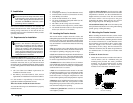
2.2 Locating the Prosine Inverter
The inverter utilizes complex electronic circuits, and
although design precautions have been made for protection
of these circuits, they can be susceptible to damage from
use in extreme environments. The Prosine Inverter should
only be installed in a location that meets the following
requirements:
• Dry:do not allow water or other fluids to drip or splash
on the Prosine Inverter. Do not mount the inverter in an
area subject to splashing or dripping water or bilge.
• Cool: normal ambient air temperature should be between
0°C (32°F) and 25°C (77°F)—the cooler the better within
this range. Refer to the operating temperature information
in section 9 (specifications) for more details.
• Ventilated: allow at least 5 inches (13 cm) of clearance
all around the unit. Ensure the ventilation openings on the
unit are not obstructed. If mounting in a compartment,
ventilate with louvers or cut-outs.
• Safe: do not install the Prosine Inverter in the same
compartment as batteries or in any compartment capable
of storing flammable liquids such as gasoline. Do not
install the inverter in an engine compartment or other
location where ignition protected equipment is required.
• Dust-free: do not install the Prosine Inverter in a dusty
environment where either dust, wood particles or other
filings/shavings are present. These can be pulled into the
unit when the cooling fan is operating.
• Close to AC junction box: avoid the use of extended
wire lengths if possible.
• Close to battery/batteries: Avoid excessive cable
lengths but do not install the Prosine Inverter in the same
compartment as batteries. Use the recommended wire
lengths and sizes (see section 2.4.4). Also do not mount
the inverter where it will be exposed to the gases
produced by the battery. These gases are very corrosive
and prolonged exposure will damage the inverter.
• Protected from battery acid: never allow battery acid
to drip on the Prosine Inverter or its wiring when reading
specific gravity or filling the battery.
2.3 Mounting the Prosine Inverter
Before mounting the Prosine Inverter, test the chosen
location for adequate space around the unit to allow for
connections and ventilation. Mounting hardware should
be corrosion resistant and ¼” or 6mm diameter screws.
Your mounting system should be able to support three
times the weight of the inverter, which weighs
approximately 16 lbs (7.3Kg). The more clearance for
ventilation around the unit, the better the performance.
At a minimum, have 5” of free space on all sides of the
inverter.
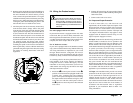
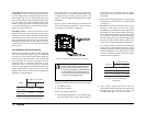
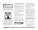
To mount the Prosine Inverter
1. Mount the Prosine Inverter on either a horizontal or
vertical surface (such as a bulkhead) using the
mounting holes provided. For secure, permanent
mounting, use all eight mounting holes. To meet
regulatory requirements, the inverter must be
mounted in one of the three orientations shown.
CAUTION
The Pro sine Inverter is designed to be
permanently connected to your DC electrical
system. When Configured as an AC hardwire
version, the inverter is also designed to be
permanently connected to your AC electrical
system. To ensure adherence to proper electrical
wiring regulations, all wiring must be done by a
certified technician or electrician.
WARNING
Review the Important Safety Instructions found
at the beginning of this manual and read this
entire section, paying particular attention to the
CAUTION and WARNING statements, before
proceeding with the installation.
Figure 1. Approved orientations for
inverter mounting