


10 English
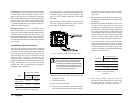
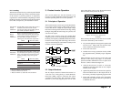
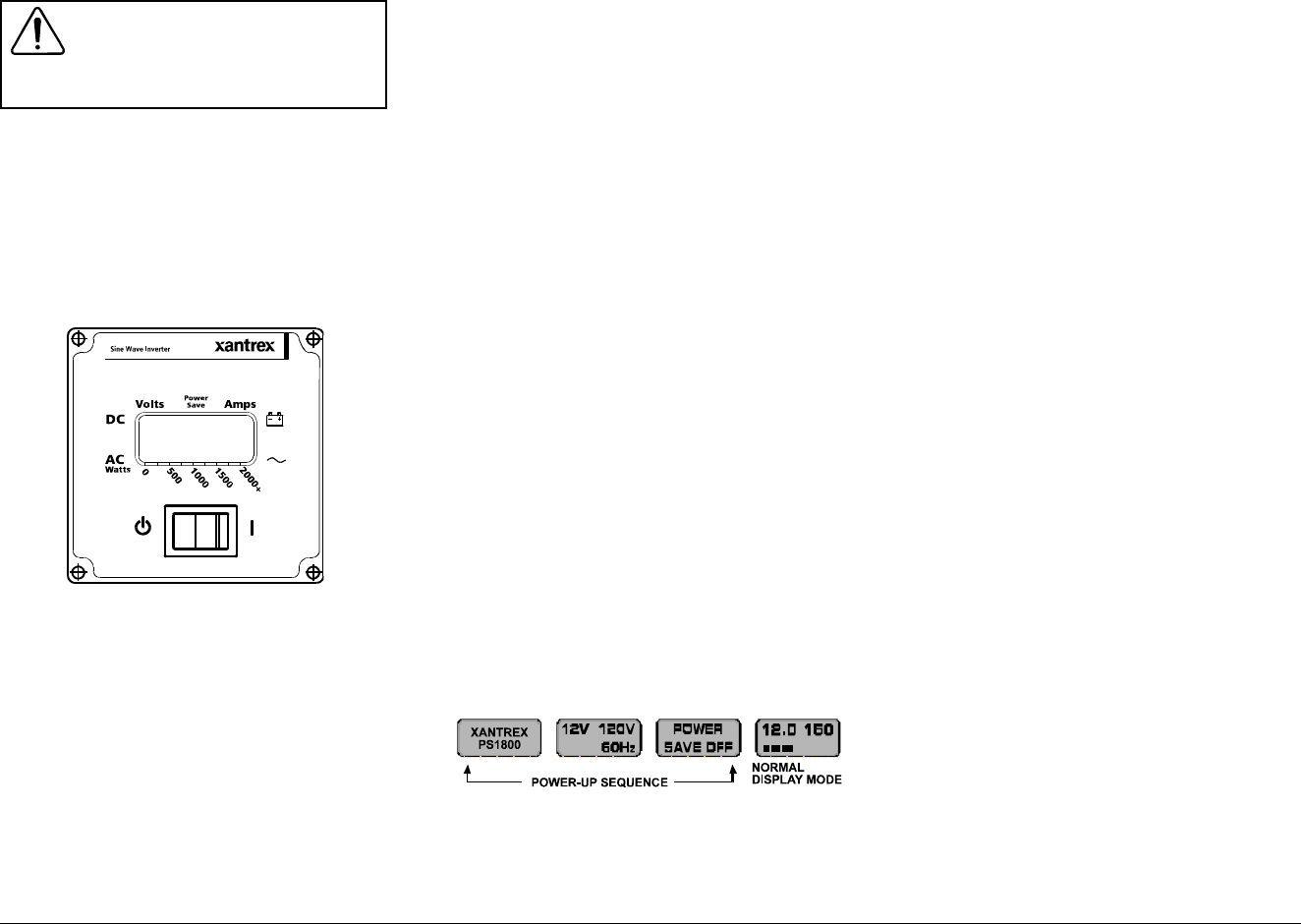
3.3 Control Panel
Once the Xantrex Prosine Inverter is properly installed
and connected to batteries, it is ready to begin delivering
AC power to your loads. The control panel is the
interface between you and the inverter. This section
describes the features of this panel and is followed by
other sections that contain inverter operating
information.
1. INVERTER
##
##
#/I: this switch turns the Prosine
Inverter either ON (I) or to BYPASS-state (
##
##
#). It is
also used to enable or disable POWERSAVE mode
during the power-up sequence. When in the (
##
##
#)
position, models equipped with a transfer relay will be
in the BYPASS mode, where incoming AC power is
passed through to the load. The switch controls the
output of the inverter with models equipped with AC
outlets and does not control the output on hardwire units
equipped with the transfer relay option.
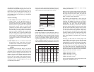
2. LIQUID CRYSTAL DISPLAY (LCD): displays
input current from the battery and battery voltage
numerically. A multi-segment bar graph displays actual
output power in watts from the inverter when a load is
being operated.
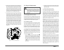
3. MULTI-POSITION MOUNT: the control panel is
designed so it can be removed and re-attached to the
chassis in 90° increments depending on the mounting
orientation of the inverter itself. The panel can also
be removed entirely from the unit and mounted
remotely, with the purchase of the optional Interface
Panel.
4. FAULT CONDITION DISPLAY: should a fault
occur, the error will immediately be displayed. An
audible alarm sounds and the back-lighting of the
display will flash to draw attention to the fault
condition (see Section 5.1).
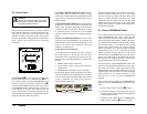
To operate the Prosine Inverter:
1. Turn the unit ON by moving the rocker switch on
the control panel to (I) position. The following
information will be displayed (upon each power-up),
identifying the type and configuration of your Prosine
Inverter:
• Model number (1000 or 1800 watt)
• Input Voltage, Output Voltage and Frequency
configuration
• POWERSAVE mode OFF (factory set default)
Following the display of this information, the control
panel then defaults to the standard display information
of input voltage, input current and output power. When
a load is connected, the output power (watts) is
displayed in bar-graph form.
WARNING
Review the Important Safety Instructions
found at the beginning of this guide before
operating the Prosine Inverter.
Once the standard display screen is shown, the Prosine
Inverter is ready to deliver AC power to your loads.
You can now plug in a load to the front outlet of the
unit, or, for those hardwire versions, into an outlet
connected to the AC output of the inverter. The loads
should operate from the inverter as they would from
utility power. Section 3.5 explains the operating limits
for the Prosine Inverter.
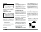
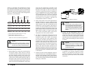
3.4 Prosine POWERSAVE Mode
Your Xantrex Prosine Inverter has a function mode
called POWERSAVE. This “sleep” mode shuts off
much of the power control circuitry of the inverter as
well as the display back-lighting, reducing the stand-
by current draw considerably. With this mode enabled,
the unit draws approx. 1.5 W while powered up but
with no load on the inverter. The Prosine Inverter
detects the presence of a load by sending out pulses
approximately once every 2.5 seconds. Full output
power is available with the detection of a load. The
unit will remain in POWERSAVE mode if the load it
detects is less than 10 W for the 1000 model and less
than 20 W for the 1800 model. This is a factory set
search mode setting and cannot be changed.
You would want to enable POWERSAVE mode if the
inverter is only being used periodically to power loads.
This allows the inverter to draw less power from the
batteries during non-use periods. If the inverter is being
used frequently and your batteries are being recharged
during inverter use (e.g. vehicle alternator), or soon
after inverter use, you can leave POWERSAVE
disabled.
Your inverter is factory default set to POWERSAVE
OFF. To enable the POWERSAVE mode, follow these
steps:
1. Turn the Control Panel switch to (
##
##
#) position
2. Switch the unit back to (I) position. You will see
the power-up information sequence being displayed
as described previously.
3. When the Control Panel displays “POWERSAVE
OFF” turn the switch to (
##
##
#) position, wait for
Xantrex Prosine Inverter Owner’s Manual
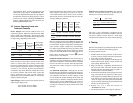
Figure 7. Control Panel
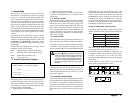
Figure 8. Control Panel Screen Sequence