


Features
2–2 975-0376-01-01
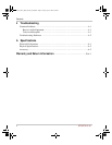
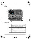
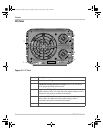
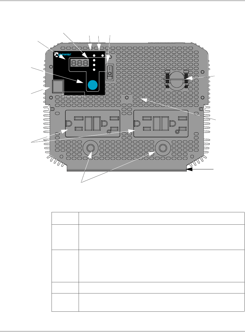
AC Panel
Figure 2-1
AC Panel
Feature Description
1 On/Off Switch turns the inverter’s control circuit on and off. This
switch is not a power disconnect switch. Disconnect DC power
before working on any circuits connected to the inverter.
2 Fault light (red): indicates the inverter has shut down due to
inverter overload, over-temperature, under voltage, over voltage, AC
output short circuit, or AC back-EMF (backfeed) protection
shutdown.
3 Power light (green): indicates the inverter is operating.
4 Status indicator lights: VOLTAGE, CURRENT, AC POWER
When lit, each light indicates which status is being displayed.
REMOTE
SWITCH
DISPLAY
FUNCTION
VOLTAGE
CURRENT
AC POWER
V
A
kW
POWER FAULT
INVERTER
5000
20A 20A
5
6
8
10
1
23
4
7
9
11
12
XPower_Inverter_5000_Owners_Guide.book Page 2 Friday, April 4, 2008 2:59 PM