


Features
2–4 975-0376-01-01
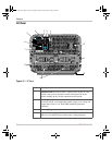
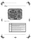
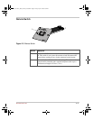
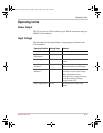
DC Panel
Figure 2-2
DC Panel
Feature Description
1 Chassis Ground Lug connects to vehicle chassis.
2 Ventilation Opening and Fan Assembly must not be obstructed
for the proper operation of the inverter.
3 Negative (–) DC Input Terminal connects to one end of the
negative battery cable. The other end of the negative battery cable is
connected to the negative terminal of the battery.
4 Positive (+) DC Input Terminal connects to one end of the positive
battery cable. The other end of the positive battery cable is
connected to the positive terminal of the battery.
5 Serial number of your inverter.
DANGER:
Thisunitemployscompo-
nentsthattendto producearcsor sparks.
Riskof fireandexplosion– Donot install
near batteries, in machinery space, or
area in which ignition-protected
equipmentis required. Shock Hazard–
Do not open. No serviceable parts inside.
INPUT: 12 Vdc (nominal),
520 A (5 min. max.) / 415 A (cont.)
OUTPUT: 120 Vac / 60 Hz
5 kW / 41 A (5 min max.)
4 kW / 33 A (continuous)
CHASSIS GND
SerialNo.
BATTERY
NEG.
BATTERY
POS.
WARNING:
Shock,energy,andfirehazards. Readmanualbeforeinstallingor using.To preventfire,donotcoveror
obstructventilationopenings. Do not mountin zero-clearancecompartment. Overheatingmay result. Donot exposeto rain or
spray. UseGroundFaultCircuitInterruptersonlyas specifiedinthemanualssuppliedwiththisunit. Othertypesmayfailtooperate
when connected to this unit. Ensure proper grounding.Total harmonic distortion is 38%; maximum single harmonic is 32%.
Patents Pending
Designed in Canada by
Xantrex / Assembled in China
1
2
3
4
5
XPower_Inverter_5000_Owners_Guide.book Page 4 Friday, April 4, 2008 2:59 PM