Overview and Operation 9
English 202052A
Check the 3M
TM
SpotOn
TM
Temperature Monitoring System website to ensure you have the most recent version of this document. www.spotontemperature.com reorder #202052ACheck the 3M
TM
SpotOn
TM
Temperature Monitoring System website to ensure you have the most recent version of this document. www.spotontemperature.com reorder #202052A
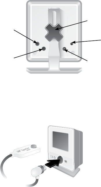
Back of Control Unit
To view information and connections on the back of the control unit, assure that controller is viewed
from a distance no further than 15” (38 cm) from the operator.
Stand Knob
°C/°F Temperature
Display Button
Power Input Port
Digital Port
(used by 3M personnel only)
Monitor Cable Port
Figure 5: Back of Control Unit
e digital port is used only by 3M Patient Warming personnel for testing purposes and to access
variables within the control unit.
e monitor cable port provides a resistance that corresponds to a YSI-400 thermistor at the displayed
temperature. It is electrically isolated from the SpotOn control unit.
Front of Control Unit
Setting up the SpotOn control unit
1. e SpotOn control unit must be properly installed and mounted by qualied personnel.
NOTE: e SpotOn sensor and control unit are suitable for use in the patient environment.
2. Connect the power supply to the back of the SpotOn control unit (see Figure 5: Back of Control
Unit).
Plug the power supply into an appropriate outlet. e standby screen will illuminate.
3. Connect the SpotOn sensor cable to the front of the control unit. See Figure 6: Front of Control
Unit for proper orientation and connection.
4. If desired, use the provided monitor cable to connect the SpotOn control unit to the patient
monitor
(see Figure 5: Back of Control Unit).
NOTE: Temperature input on patient monitor typically labelled T1 or T2.
Figure 6: Front of Control Unit


