


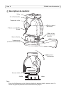
Page 8 YP3040 Installation Guide
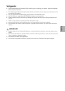
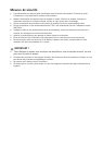
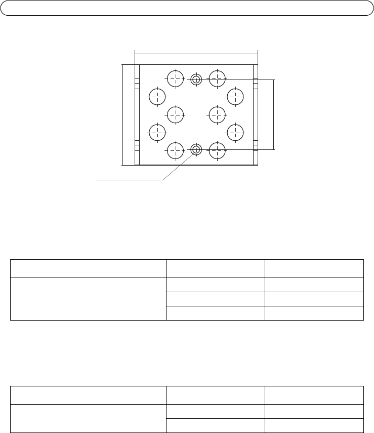
Splint dimensions
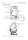
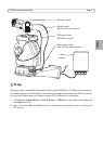
Connect the cables
1. Connect the power supply to the pan-tilt motor according to the Installation Guide supplied
with the mains adaptor. The recommended mains adaptor is AXIS PS24 Mains Adaptor. For
more information on this product, see the Axis web site at www.axis.com
2. Connect the PTZ control cable to the camera’s RS-485 port. Different camera models have
different terminal connectors, be sure to follow the correct description for the installed camera.
The correct connector is supplied with the Axis network camera. For more information on Axis
network cameras, see the Axis web site at www.axis.com
3. Connect the camera to the network, see the Installation Guide provided with the camera.
Note:
The RJ-45 connector for the network cable will not pass through the cable gland on the
underside of the housing. The cable must be cut, threaded through the cable gland and
then re-crimped.
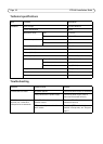
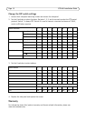
Wire color Connect to
Power supply cable 24 V AC Blue 24 V AC on power supply
Brown 24 V AC on power supply
Yellow/green GND
Wire color Connect to
PTZ control cable (RS-485) Red A+ on camera
Blue B- on camera
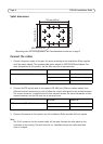
122 mm (4.8 in.)
Ø 6 mm (0.2 in.)
100 mm (3.9 in.)
70 mm (3.9 in.)
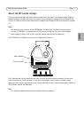
Mounting holes for housing/camera, see Recommended accessories, on page 3