


Technical Services Group ~ 1-800-283-5936 (USA) ~ 1-801-974-3760
This chapter provides step-by-step instructions for installing your GT1524 system.
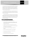
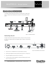
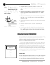
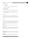
Figure 2.1 (below) shows the back panel connections of a fully-installed GT1524
system.
Connecting the unit
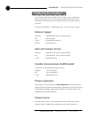
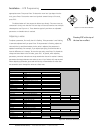
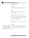
The power cord should be connected last. Otherwise, the order in which you connect
the cables is not important. Refer to the diagram shown in Figure 2.2 when making
connections.
1. Place the unit in a standard 19-inch rack and attach it securely.
2. Connect your telephone line from the wall jack to the RJ-11 Line jack [H].
3. Plug your telephone set into the RJ-11 Set Jack [I].
4. If you are using a custom controller for control and status, plug it into the
DB-25 Control/Status port [F].
CHAPTER 2: Installation
LINE OUT
AUX OUT
4 WIRE/VIDEO CODEC
OUT
IN
AUX IN
MIC/LINE IN
Logic out
status and
control
Analog
Telephone
Line
5W, 8Ω
Speaker
Power Amp
Video codec
Microphone
M
U
T
E
I
N
U
S
E
R
E
A
D
Y
AP IR Remote Control
Figure 2.1. GT1524 installation
Hardware Setup
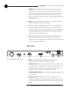
AB C D EF
GH
I
Figure 2.2. GT1524 Rear panel connectors